• The move to the new server is done. There are some software and database maintenance updates in process. This has us passing the hat around to help out. We appreciate any donations. Seriously, even a dollar helps. The payment page may be found here - https://www.audiokarma.org/support.html

Marantz 2500 repair help

left channel 65mv minimum it can get to, and the right channel 35mv maximum on a 200w dim,
Thinking out loud...
Need to further reduce left channel by adding "resistance".
Right channel can be adjusted to the wanted 25mV

currently can only reach 16mv on one channel and 25mv on the other at max trim pot adjustment however r721 currently modified to 330ohm instead of 180ohm
Using a 300w globe or just a variac up to 220v, I still cannot get bias above 20mv or so on each channel, I’ve replaced resistor r721 previously from 180 to 330 ohm,
The DBT may be causing you issues, while the DBT might not be very bright it will have a volt drop, that should have been passed onto the amp, ie, the rails are not at full voltage so no surprise you can't adjust the bias point, designed for full rails voltage, ok, get it wrong and you have meltdown.

Think you need to convince yourself that it's safe to power up without dbt. Do this by powering up one (only) power amp board first on DBT then without. Repeat for other side, if ok then both together without dbt.
 
Thinking out loud...
Need to further reduce left channel by adding "resistance".
Right channel can be adjusted to the wanted 25mV


The DBT may be causing you issues, while the DBT might not be very bright it will have a volt drop, that should have been passed onto the amp, ie, the rails are not at full voltage so no surprise you can't adjust the bias point, designed for full rails voltage, ok, get it wrong and you have meltdown.

Think you need to convince yourself that it's safe to power up without dbt. Do this by powering up one (only) power amp board first on DBT then without. Repeat for other side, if ok then both together without dbt.
Sorry Mbz I was tired last night and misspoke,
Right channel 25mv is the minimum bias and left channel 70mv minimum bias with a 200w globe I will try with the 300w to see any difference but with my previous tests I didn’t see any change here to the results. The right channel didn’t respond any different when replacing with a like bias transistor as per left channel yesterday.

Minimising one channel bias raises the other and vice versa but the minimum points are obviously too high on the left side, Minimising right channel to 6mv raises left to over 100mv minimum for example.

I noticed for both channels adjusting the trimmer in one direction does not create a linear change ie it may increase but then decrease mv despite going in same direction for adjusting the trim pot.

Prior to replacing q705-8 I was able to bias ok atleast with reasonable range even with a 150w dim before the meltdown and resistor change so I understand what you’re saying about the rail voltage but as you and dankik said previously I think the 330ohm resistor was hiding another issue?

I’m inclined to revisit the substitution for q705-8 as I need to pull the boards off again anyway, currently ksa1381/ksc3503 thinking to try ksc2690/ksa1220. Thoughts?

It’s difficult to test one channel on its own keen to hear your thoughts on above before attempting a one channel approach
 
Minimising right channel to 6mv raises left to over 100mv minimum for example.
Not a good sign maybe suggesting a potential runaway situation if powered up without DBT.
I thought the amp was mostly stable, needing a minor tweak, appears we are still at the stage of one channel is unstable.
Need to keep it on dbt until amp is stable.

I’m inclined to revisit the substitution for q705-8 as I need to pull the boards off again anyway, currently ksa1381/ksc3503 thinking to try ksc2690/ksa1220. Thoughts?
I'm against replacing transistors in hope

Give me a bit of time I will run some simulations (microcap 12)
 
I ran some scenarions in MC12(*), bias set to 25.3mV
- STV4, 1 diode short... bias approx 0mV
- STV4, 1 diode open.... bias approx 1V
- R721(180) short....... bias approx 40mV
- R721(180) open........ bias approx 0mV
- Q705,6 change from KSA1220 to KSA1381...voltages change, bias approx 22mV
- Q707,8 change from KSC1815 to KSC2690...voltages change, bias approx 27mV
- Q707,8 change from KSC2690 to KSC3503...voltages change, bias approx 24mV

takeouts
changing Q705...8 will give a minor change
Intermittent/open STV4 will give a dramatic change

Candidates IMO are Qm01(STV4), R758(150), Q732 and associated tracks/solder joints, if anything in this path goes intermittent/open then you will have meltdown

* I've only just started using MC12
 
I ran some scenarions in MC12(*), bias set to 25.3mV
- STV4, 1 diode short... bias approx 0mV
- STV4, 1 diode open.... bias approx 1V
- R721(180) short....... bias approx 40mV
- R721(180) open........ bias approx 0mV
- Q705,6 change from KSA1220 to KSA1381...voltages change, bias approx 22mV
- Q707,8 change from KSC1815 to KSC2690...voltages change, bias approx 27mV
- Q707,8 change from KSC2690 to KSC3503...voltages change, bias approx 24mV

takeouts
changing Q705...8 will give a minor change
Intermittent/open STV4 will give a dramatic change

Candidates IMO are Qm01(STV4), R758(150), Q732 and associated tracks/solder joints, if anything in this path goes intermittent/open then you will have meltdown

* I've only just started using MC12
Thanks MBZ this is awesome analysis here!

I have refitted original stv4 and new 150ohm resistors and checked for continuity in the associated areas - all seemed ok but to rule out doubt replaced them anyway also q732 was already new.

Found two questionable joints on collectors on Jm05/6 but really knit picking there reflowed them anyway

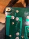
I noticed a plastic washer on one of the metal tabs that is used to screw the p700 board to the heat sink board, the metal tab connects to the bases of the outputs transistors on one side it seems that it’s not needed as the second tab does not have the washer and they are connected together? Does anyone know if plastic washers are in fact needed for these 4 tabs? I doubt it but thought I’d check before reassembly only one is present I had previously removed of the other channel already thinking it was grime
 

Attachments

  • IMG_4058.jpeg
    IMG_4058.jpeg
    161.3 KB · Views: 18
  • IMG_4060.jpeg
    IMG_4060.jpeg
    103 KB · Views: 19
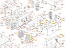
This is from the 2500 SM. There doesn't appear to be any plastic washer on that tab on 133G. There are metal tabs that connect to the screws that hold the P700 board to 133G & 134G. That plastic washer looks like part 135G in the drawing. Check to make sure that you have all of those installed. Or it might me one of the insulators for the transistor screws to prevent the power transistors from shorting to the heatsink.

1728400539726.png
 
This is from the 2500 SM. There doesn't appear to be any plastic washer on that tab on 133G. There are metal tabs that connect to the screws that hold the P700 board to 133G & 134G. That plastic washer looks like part 135G in the drawing. Check to make sure that you have all of those installed. Or it might me one of the insulators for the transistor screws to prevent the power transistors from shorting to the heatsink.

View attachment 3314768
Thankyou Dankik I didn’t see this page in the manual the pdf sometimes crashes my phone and I can view only some pages looks like no need for the plastic washer on j710 as suspected good news all the plastic bushings are there for the output transistor screws I’ll remove this bit and reassemble and test
 
Some good news to share, initial signs after 20 mins both channels are showing consistent bias, steady and a non bright 200w globe, will try a 300w globe and then full mains but there is good bias range adjustment now and both channels are even! Thankyou everyone for your help on this project it’s been a huge undertaking and I’ve learnt a lot from this experience very grateful to the members and knowledge here at AK
 
The 2500 continues to work well, I thought I’d summarise a few learnings for anyone who undertakes a restoration on one of these in future

- always double check the original polarity of capacitors don’t go off the boards there are a lot of errors mainly on power supply board
- always discharge the main caps before disassembling the main amp modules the bleeder resistors do not bleed the positive rail
- check over the solder joints and tracks to all the pins on the main amp boards these can fracture easily after disassembly
- recommend removing the transistors sockets that hold the bias transistor and driver transistors and hard wiring then to the boards, when doing so make sure the joints are solid and legs do not touch each other, these sockets were intermittent for me and caused endless issues…
- if doing any testing with a dim bulb and all is working properly you should be able to bias both channels with reasonable range - but obviously do it properly without dim after…minimum 150watt needed
- replace all the trimmers - especially the amp module ones which cop the most heat
- work with caution around the tube and power supply high lethal voltages there

Thanks again to all that assisted on this journey
 
  • Like
Reactions: mbz
Back
Top Bottom