• The move to the new server is done. There are some software and database maintenance updates in process. This has us passing the hat around to help out. We appreciate any donations. Seriously, even a dollar helps. The payment page may be found here - https://www.audiokarma.org/support.html

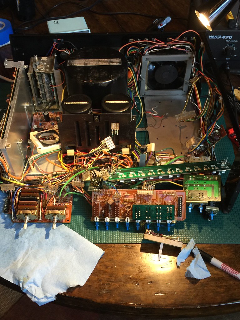
Marantz 2500e.. needs a bit of elbow grease

It's nasty to get out, I've done it as I had weak FM too. It turns out the very first amp stage FET was blown. Then I had to get the board out as well, more fun! It's a dual gate FET and very rare these days. I got one from Consolidated I think it was. I'd leave it in unless I really had to get it out. Give the chemicals a day to work, maybe it will improve. Fingers are crossed!

I have cleaned and lubed the cap several times and the reception is getting only slightly better. At the low end of the scale I can get OK signal and several channels come in stereo. Once I get over 100 Mhz the strength drops off to the point I can't get any channels in stereo. I guess this means that the cap may still be dirty? I have been using faderlube on the ground wipers followed by Deoxit Degreaser Wash... Tonight I put a bit of D5 on the wipers, I think it may break the corrosion down a bit more.

When you had the problem with the FET, how bad was the reception?

I have not done much of any tuner work... I do have a Sencore SG165 that I can use to try and diagnose the issue. Really I just want to try and figure out if it's a problem with a dirty cap, bad alignment or bad component. Maybe it's a combination?
 
The problem I had was it was just weaker all over and hardly went into stereo.

Since you have the SG165 you can inject the IF signal by removing the center conductor where it hits the IF board which I'm remembering as being in the back and down low and connecting the output of the generator to those terminals with the selector set to "10.7 MHz IF" and I believe the output scaler should give you stereo lock down into the X10 range. Make sure the pilot rocker switch is set to 10% (max).
 
Still working on the tuner issue. I ordered up some fet's, I hope they do the trick!

In the mean time I thought it would be a good time for some before, during and after pics...


As shown on ebay...

17094004805_8dae21ae48_b.jpg


17094009115_57a7dc6409_b.jpg


At home naked...

16976292897_ba724ee1d8_b.jpg


The fun begins...

17353301050_33e5de4ca6_b.jpg


Time for a bath... (really, it needed a disinfecting)

17092714560_4354207253_b.jpg


it's looking cleaner... But still has a long way to go till it makes music again.

17278446702_bceb82448e_b.jpg


Boards... hungry for new caps...

17254282876_82f99039fd_b.jpg


A sample of the 100+ caps...

17353315360_f1c35ddb26_b.jpg


It's getting better but still needs work.

16657808604_d54af7f2da_b.jpg


Now it's getting serious.. The front frame needed to come off to really get access to all of the boards. At this point I am starting to wonder if it's ever going to go back together...

17189201849_012893b3db_b.jpg


17353307400_cb64fed947_b.jpg


Getting close!

17187613328_4f63968eea_b.jpg


It's alive!
17540768171_3b8f5d23f7_b.jpg


A few tweaks...

16920578873_40908a4cd0_b.jpg


Back in one piece...

17353331110_ed73a58327_b.jpg
 
That came out AWESOME! Very nice there 'tx'! :thmbsp::thmbsp::thmbsp:

Honestly... Without your previous rebuild thread I don't think I could have done it... Thanks for your help!

I still need to:

1. Fix the tuner sensitivity
I am really not looking forward to pulling the tuning cap... I still have not tried to inject the signal as you had suggested. I will try it in the next couple of days.

2.Re stuff the big caps
3.Repaint and resticker the transformer
4.Figure out a solution for the missing balance lettering...

My brother let me use his pair of Martin Logan SL3's to listen to it. It really sounds fantastic just hooked up to an iPhone.
 
Nicely Done!!!

VERY impressive. Successful rehabilitation of Marantz scope receivers takes extreme patience and attention to detail. My hat's off to you!! :tresbon:
 
Excellent work Dr. Frankenstein. Your monster breaths from your deft surgery. May your continued FM experiments lead to success.
 
Yes! Nice job! Just a suggestion, look into the soft white LEDs they give a more authentic glow.

Thanks!


The ones I purchased should be "soft white" according to the auction.. I never did power them outside of the housing though... I got an extra lamp so I think I'll power it up and take look.
 
I know obscenity is an idiot trying to be emphatic, but that is fcuking awesome.


VERY impressive. Successful rehabilitation of Marantz scope receivers takes extreme patience and attention to detail. My hat's off to you!! :tresbon:

Excellent work Dr. Frankenstein. Your monster breaths from your deft surgery. May your continued FM experiments lead to success.

:thmbsp:

Tom

Wow....another beautiful transformation!


Wow!! Great job!


Thanks to all!
 
Last edited:
The problem I had was it was just weaker all over and hardly went into stereo.

Since you have the SG165 you can inject the IF signal by removing the center conductor where it hits the IF board which I'm remembering as being in the back and down low and connecting the output of the generator to those terminals with the selector set to "10.7 MHz IF" and I believe the output scaler should give you stereo lock down into the X10 range. Make sure the pilot rocker switch is set to 10% (max).

So I tried to run the test you suggested:

I removed the connection from J201 on the IF board and connected the SG165 up to it.

I am using the 39G43 matching pad's un balanced connection (red to the IF in and black to ground).

I can get stereo lock at 70 microvolts. So I am in the 10X range.

I purchased a couple of the FET's from consolidated... Time for the surgery! :smoke::smoke:
 
Prep the patient for surgery:

17787982875_9b12d96b71_b.jpg


This is a good time to clean the old flux off the back of the from end board.

17167699553_9bba24bbc9_b.jpg


Found a clue....

17785337932_deb9256736_b.jpg


It looks like someone may have been in in the front end before me. The FET in the first stage (Q101) is a 3K48N.. I am not even sure what it is...

The second and third stage FET's have a colored marking on top of them. I can't really see the part number without removing them.

time to install the new FET
 
Last edited:
So... I replaced all three FET's yet I still get the same result. Really weak sensitivity.

If I set the dial to 88mhz or so and provide an RF signal with the SG165 as I increase the output to the upper 100 x microvolt range I can see the AGC voltage start to drop from 2.5v down to a low of about 2.2v with the generator in the 1000x range.

Could it be that the cap is still dirty? Maybe the alignment is just way out?
 
Hmm, not much AGC action there. I think mine went down to near zero volts, I just don't remember. Maybe I still have notes in the 2500 folder but I'm at work. I'll check. Did you verify that the fine center wire on the coax from the front end's output to the IF board input isn't broken at either end?

Mine had the painted top FETs in it too, maybe they were factory tested with the best parts going more towards the front end. The '48's I believe are still dual gate MOSFETs.
 
Finally found the info right in the rebuild thread I had posted. Once the first stage blown FET was replaced, I had found a cracked trace right after the input down on the IF board. Once all was well the AGC ranged from 2.35Vdc on a strong station and went down to 1.25Vdc off tune. So it seems your issue is in the front end then.

I'm attaching a scan of a marked up front end schem. with voltages I either calculated or recorded. Hope it helps!
 

Attachments

There may be more than one version of the FM circuitry in the 2500s. On Randy's 2500, the AGC voltage was positive, on the one I worked on it was negative. Read about that starting at post 126 in Randy's excellent rebuild thread.

Tom
 
Back
Top Bottom