
• The move to the new server is done. There are some software and database maintenance updates in process. This has us passing the hat around to help out. We appreciate any donations. Seriously, even a dollar helps. The payment page may be found here - https://www.audiokarma.org/support.html

Marantz 4300 - Missing 10v in Power Supply

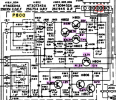
As a first pass, trace the connections on the schematic, there will be (?) a local resevoir cap and noise bypass cap on that rail, these would be candidates.

Is the J801/J034 connector(?) unpluggable or is it wire wrap pins. Worth unplugging then dbt power up????
The reservoir cap is a 1000uF 63v that seems to test okay - reading 47v on positive terminal. Not sure which cap is the noise bypass cap but I've tested the rest and nothing stands out.

The J801 connector is removeable - with it removed on DBT I can take the voltage measurement from here - and I get almost 28v as opposed to the 24 or so before.
1769284990996.png
 
The J801 connector is removeable - with it removed on DBT I can take the voltage measurement from here - and I get almost 28v as opposed to the 24 or so before.
Is the DBT dim? Wind back voltage to about 20V then try power up with unplugged connector and no DBT, you should then be able to adjust to above 35V
 
Is the DBT dim? Wind back voltage to about 20V then try power up with unplugged connector and no DBT, you should then be able to adjust to above 35V
DBT is dim - I removed it from DBT and the furthest I can adjust to with J801 removed is that 28v on mains. :(
 
  • Like
Reactions: mbz
DBT is dim - I removed it from DBT and the furthest I can adjust to with J801 removed is that 28v on mains.
Means the power supply is sick. H803 Vbe will be too high. The emitter voltage is set by zener H808, base voltage from VR/R806. I assume you've replaced everything (silicon.caps,VR..) in this area.

As a baseline, with connector still unplugged, measure H803 b/c/e voltages. I'd be then tempted to replace zener H808 with an 8V(abouts) item, wind back the VR before power up. The idea is to lower H803Vbe.

What transistor did you use for H803.
 
Means the power supply is sick. H803 Vbe will be too high. The emitter voltage is set by zener H808, base voltage from VR/R806. I assume you've replaced everything (silicon.caps,VR..) in this area.

As a baseline, with connector still unplugged, measure H803 b/c/e voltages. I'd be then tempted to replace zener H808 with an 8V(abouts) item, wind back the VR before power up. The idea is to lower H803Vbe.

What transistor did you use for H803.
J801 still removed - remeasuring H803
B 25.6v
C 28.3v
E 6.83v

H803 was replaced with a 2sc945

I had replaced H808 with a 7.2 or 7.4 v zener I had. I will replace with an 8volt zener and report back
 
Means the power supply is sick. H803 Vbe will be too high. The emitter voltage is set by zener H808, base voltage from VR/R806. I assume you've replaced everything (silicon.caps,VR..) in this area.

As a baseline, with connector still unplugged, measure H803 b/c/e voltages. I'd be then tempted to replace zener H808 with an 8V(abouts) item, wind back the VR before power up. The idea is to lower H803Vbe.

What transistor did you use for H803.
I installed an 8.2v zener in H803 - powered up on dbt with J801 still disconnected, highest I can adjust is still 28v.
 
  • Like
Reactions: mbz
J801 still removed - remeasuring H803
B 25.6v
C 28.3v
E 6.83v

H803 was replaced with a 2sc945
H803 should be toast, datasheets show max Vbe of 5V, you've got 19V!
But the real problem is why H803b is 25V, again no current flow through R805 because of alternate low resistance path from H801e to GND. Going in circles a bit. Only if it's reasonably easy to do, post high res pix of the P800 board both component and solder side
 
H803 should be toast, datasheets show max Vbe of 5V, you've got 19V!
But the real problem is why H803b is 25V, again no current flow through R805 because of alternate low resistance path from H801e to GND. Going in circles a bit. Only if it's reasonably easy to do, post high res pix of the P800 board both component and solder side
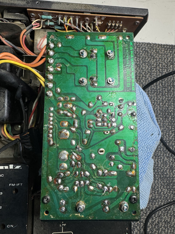
Here is a link to high res pics of front and back of P800.

Thanks again.

 
Will study pix shortly, thx

Was thinking, pull H803, zener H808 and C807(10uf/50V).
With J801 disconnected, dbt power up, expect bulb dim then power up without dbt.
You should have about 42V at H801e
 
If it's that torn pad that looks like it's bridged I assure you it is not, just funny looking in picture.
Yeah, that's the one, it wouldn't give the symptoms you are seeing.
If you are up for it pull parts as per post #29
 
Yeah, that's the one, it wouldn't give the symptoms you are seeing.
Will study pix shortly, thx

Was thinking, pull H803, zener H808 and C807(10uf/50V).
With J801 disconnected, dbt power up, expect bulb dim then power up without dbt.
You should have about 42V at H801e

If you are up for it pull parts as per post #29
H803, Zener H808, and C807 pulled, J801 disconnected.

Powered on with DBT I am getting almost 51 volts on H801e. :yikes:
 
Powered on with DBT I am getting almost 51 volts on H801e.
OK a little higher than expected but power supply is totally unloaded. Schematic shows H801c at 44V that's why I ballparked 42V.

Plz note voltage at R806 wiper or H803 base tab, expect somewhere between 11&17Vdc depending on VR position. Does H801e voltage change with R806 adj?

If as expected then reconnect C807 and repeat R806 wiper voltage measurement
 
OK a little higher than expected but power supply is totally unloaded. Schematic shows H801c at 44V that's why I ballparked 42V.

Plz note voltage at R806 wiper or H803 base tab, expect somewhere between 11&17Vdc depending on VR position. Does H801e voltage change with R806 adj?

If as expected then reconnect C807 and repeat R806 wiper voltage measurement
R806 wiper voltage is right around 17volts - H801e voltage does not change when R806 is adjusted.
 
That's ok, my bad. Expect wiper voltage to change with VR adj, you should get down to about 11 volts, if so reinsert C807 and repeat
Okay, with C807 reinstalled, J801 still detached, I can get wiper voltage down to 9 volts with VR - R806
 
  • Like
Reactions: mbz
Great. Measure the H801e to GND resistance, wanting to see about 32k.
Then reinstall zener H808 then recheck wiper voltage 8-9V??? and H801e to GND resistance.

I'm not sure I see the point of R804, initally I thought that it was for fine tuning, anyway connecting up the zener opens this path.
 
Great. Measure the H801e to GND resistance, wanting to see about 32k.
Then reinstall zener H808 then recheck wiper voltage 8-9V??? and H801e to GND resistance.

I'm not sure I see the point of R804, initally I thought that it was for fine tuning, anyway connecting up the zener opens this path.
I'm getting a reading of 3.3 megaohms from H801e to gnd before re-installation of zener H808.

After the reinstallation of the zener I get a reading of 92 megaohms to ground on h801e

Wiper voltage is the same and changes with the adjustment of R806 still.
 
Nah, must be measurement error on the resistance.

So you can still get about 8V at the wiper. Can you install a new 2SC945 (H803) and before power up check that H801e to GND resistance, don't want to see less than 3.3k. Reverse probe polarity and recheck, zener migh be playing games. With red probe on anode expect maybe 4.5k??? Black probe on anode then 32k abouts.

If all ok then dbt power up and check wiper voltage, less than 9V? Does it respond to VR adj?
 
Back
Top Bottom