• The move to the new server is done. There are some software and database maintenance updates in process. This has us passing the hat around to help out. We appreciate any donations. Seriously, even a dollar helps. The payment page may be found here - https://www.audiokarma.org/support.html

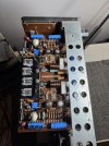
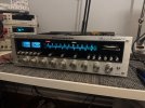
Marantz 4300 - Missing 10v in Power Supply

Are you using KSC945?. Check the basing carefully. Original 2sc945 is Collector center lead. KSC945 are base center lead. If you have KSC945C the center lead is the collector. They are all labelled "C945" and can drive you crazy if you aren't aware of the variants...My two nickels.
 
Nah, must be measurement error on the resistance.

So you can still get about 8V at the wiper. Can you install a new 2SC945 (H803) and before power up check that H801e to GND resistance, don't want to see less than 3.3k. Reverse probe polarity and recheck, zener migh be playing games. With red probe on anode expect maybe 4.5k??? Black probe on anode then 32k abouts.

If all ok then dbt power up and check wiper voltage, less than 9V? Does it respond to VR adj?
Are you using KSC945?. Check the basing carefully. Original 2sc945 is Collector center lead. KSC945 are base center lead. If you have KSC945C the center lead is the collector. They are all labelled "C945" and can drive you crazy if you aren't aware of the variants...My two nickels.


Annnnd we got it.

H803 - the 945's I installed were KSC945's - pinout EBC not ECB mixed into my bag of 2sc945's - H803 was completely shorted.

Corrected pinout and reinstalled a new 945 - voltage can now be adjusted to the appropriate 35v.

Thank you so much @mbz and @sregor

off to rebuild the amp boards now! :banana:
 
Last edited:
  • Like
Reactions: mbz
I suspect that the root cause of your problem is that repair you made is going intermittent, would explain the mega-ohm resistance measurements and the high wiper voltages which then kills H803. Try and find a solder blob to jumper to.
 
I suspect that the root cause of your problem is that repair you made is going intermittent, would explain the mega-ohm resistance measurements and the high wiper voltages which then kills H803. Try and find a solder blob to jumper to.
Well, the reason I jumped to the power supply after testing bias and offset on the right channel was because 1. - bias wasn't there and 2. - offset was swinging wildly up and down.

H803 - the 2sc945 that I had the pinout switched up on was testing as a diode. So my mistake - I believe - inadvertently caused the same problem or something similar I was experiencing initially.

I have both amp boards rebuilt now and new outputs in the left channel. One channel I can't get bias quite up to 12mv, can only get to 9 or so before it goes back down - weirdly enough not up.

No FM stereo reception or light (light is good and reception is great).

And loud pops when switching to and from quadraphonic modes.

Hopefully they aren't too serious. FM stereo issues drive me crazy
 

Attachments

  • IMG_2785.jpeg
    IMG_2785.jpeg
    143.5 KB · Views: 3
Common cause of no stereo is dirty trimmer for the PLL. R311 on the tuner board. Note or mark the position, then put a little contact cleaner on it and work it back and forth a few times.
The Bias adjustment is a very small range, and others have reported problems due to slightly higher Vbe on the driver or output transistors.
Depending on your level of OCD, I think 9 mV is okay. (but my OCD level is pretty low)
 
Common cause of no stereo is dirty trimmer for the PLL. R311 on the tuner board. Note or mark the position, then put a little contact cleaner on it and work it back and forth a few times.
The Bias adjustment is a very small range, and others have reported problems due to slightly higher Vbe on the driver or output transistors.
Depending on your level of OCD, I think 9 mV is okay. (but my OCD level is pretty low)
Deoxed and cleaned, re-adjusted but no success.

I am totally okay with 9mv as long as this is common - voltages look fine everywhere else and it seems to be behaving otherwise, - I will continue to monitor it.
(I do find it strange the one channel that wont quite come up to 12mv shows around .4mv on dbt and the other one is at the expected 12mv. Off dbt the low one is around 9 and the other is still just at 12mv, odd)

The popping when switching to quad modes is gone after deoxing the heck out of everything again, unit is squeaky quiet/clean.

Need a knob or two, and some lights. but am very happy with how it's cleaning up.

I had a bit of a pop on power on as well - changed C814 on P800 from the 220uf to 470 and all is well.
 

Attachments

  • IMG_2789.jpeg
    IMG_2789.jpeg
    205 KB · Views: 4
Last edited:
So found one other problem - was missing a channel in phono, found a bad 2sc458, replaced it and the lytics, but used 1845's and had some weird cycling in the woofers.

Guessing the HFE was too high ? Switched to 1815's and now it's fine and the channel's back

Last thing that's left is that pesky FM stereo issue. Other than that, almost ready to put the cover back on.


:beerchug:


Getting .589v on H308B and .641v on H317B.

I believe those are both supposed to be off in order for FM stereo to function.

I do see pin 8 on the HA1156 IC is getting the voltage it needs to decode stereo though.
 

Attachments

  • IMG_2803.jpeg
    IMG_2803.jpeg
    184.8 KB · Views: 4
Last edited:
Recapped the multiplex board and found some wildly out of spec caps, namely three bipolar caps hanging off the IC - 2x .22ufs and a .47. Measuring in at more than double their specified capacitance and one had an ESR of 24 ohms.

Unfortunately still no stereo.

It's the last remaining issue with this unit - and what's more frustrating - is I noted stereo FM was operating before this repair/rebuild. :(
 
So I stumbled upon catrafters great little walkthrough/breakdown of the Marantz FM stereo circuit and figured I'd leave some measurements here in the hopes that maybe a tuner expert has any advice.
This applies to the 2275, 2325 and probably the 2250B as well although some of the component designators are different.
Note: An 'ON' NPN transistor has a base voltage about 0.6V more positive than the emitter. This will cause the collector to become very near the emitter voltage.
Wire-anded: the junction of two or more components where either one can pull that point to or near ground potential.

FM Stereo MPX operation:
Intermediate Frequency (IF) signal strength is monitored by H308. If signal strength is above muting level, H308 is ON, H309 is OFF.
If there is excessive noise, then H311 is ON which is wire-anded to H309 keeping H301 (FET) OFF.
If the discriminator is outputting DC due to the tuning being off station, either H314 or H315 is ON which are wire-anded to H309 as well. This also turns H303 ON grounding Pin 8 of the decoder forcing MONO operation.
If the station is properly tuned, not noisy and the signal strength is high enough,
H308 is ON, SS OK
H309 is OFF, SS OK
H311 is OFF, Noise is OK
H314 is OFF Tuning centered
H315 is OFF Tuning centered
H317 is OFF, SS, Noise and center tuning OK then:
H301 is ON allowing audio and MPX signal to pass into the decoder.
H303 is OFF If SS sufficient for Stereo operation and MONO button is not pressed
H302 is OFF VCO runs (AM not selected)

H308 on - .598v @ base
H309 hard off
H311 hard off
H314 hard off - 10.2v on collector
H315 off? - .520 @ base - 10.2v on collector
H317 on - base @.629v
H301 - D+S - 6.5v
G- 7.12v
H303 hard off - collector @ 2.4v
H302 hard off - collector @3.33v

Thanks all.
 
I have also now tried replacing the multiplex IC after confirming R311 was letting me dial in the 19khz pilot light
 

Attachments

  • IMG_2830.jpeg
    IMG_2830.jpeg
    244.4 KB · Views: 6
I have determined my problem is the bottom core of L201 - the top core of L201 is unfortunately cracked.

My only hope for repair in this case is a donor unit, correct?
 
I have determined my problem is the bottom core of L201 - the top core of L201 is unfortunately cracked.

My only hope for repair in this case is a donor unit, correct?
I have bought slugs on Amazon that worked but it was years ago. I still have a pile, DM me if you want a couple for the price of postage.

The old "tube" style caps in can transformers are showing up bad more and more. I'm going to be lazy and not look at a schematic but if that one has that cap, it will show in the schematic. Try adding a 10-47pF cap, whatever you may have, on the bottom of the board where the cap is inside the can and see if it helps. The pinout of these cans are screwy to me so make sure you have the right pins.
 
Back
Top Bottom