
• The move to the new server is done. There are some software and database maintenance updates in process. This has us passing the hat around to help out. We appreciate any donations. Seriously, even a dollar helps. The payment page may be found here - https://www.audiokarma.org/support.html

Marantz 8B red plate

Mike Chan

New Member
Weeks ago, my Marantz 8B turned to red plate (EL34 V4A) suddenly while listening to music. The fuse blowout also.

I found that R20A 100 ohm resistor was burned, I replaced it with a new one. The music plays again for about 5 minutes. The El34 V3A turned red again and the fuse blowout again.
I checked that the selenium diode was open circuit. So I replace it with 1N4007. I adjust the bias, however after 2 minutes the El34 V4B start getting red. I switch off the Amp and take four EL34 out.

I measure the bias is -50.5 volt.
The voltage in between R31 & R32 is 470volt instead of 408 volt.
The voltage on the other end of R32 is 450volt instead of 390 volt.

Are these voltages normal or too high?
Can anybody help me to fix this problem? Thank you so much.
 
Register to hide this ad
With the output tubes removed the power supply voltages will be elevated. It’s best to run the amp on a variac at about 100VAC for a bias voltage check to keep the B+ from exceeding the rated value of the power supply caps.

For your bias measurement, it sounds like your global negative bias supply is fine but the voltage at pin 5 of each EL34 socket needs to be confirmed. If you are seeing -50V at the 3 “good” sockets and 0V at the trouble socket that may explain why that one tube is red plating.

If you have negative 50V or so at the trouble socket it could indicate a damaged EL34 or maybe another component near that socket that is damaged or out of spec.
 
Weeks ago, my Marantz 8B turned to red plate (EL34 V4A) suddenly while listening to music. The fuse blowout also.

I found that R20A 100 ohm resistor was burned, I replaced it with a new one. The music plays again for about 5 minutes. The El34 V3A turned red again and the fuse blowout again.
I checked that the selenium diode was open circuit. So I replace it with 1N4007. I adjust the bias, however after 2 minutes the El34 V4B start getting red. I switch off the Amp and take four EL34 out.

I measure the bias is -50.5 volt.
The voltage in between R31 & R32 is 470volt instead of 408 volt.
The voltage on the other end of R32 is 450volt instead of 390 volt.

Are these voltages normal or too high?
Can anybody help me to fix this problem? Thank you so much.
The 8B has individual bias pots for each tube, and the meter on the chassis has a switch associated with it that can select each of the tubes and display its bias current for the selected tube. Do the tubes all bias up properly when you go through that ritual; i.e. select a tube with the switch and adjust the pot for that tube so that the meter needle points to the proper bias point on its scale?
 
The 8B has individual bias pots for each tube, and the meter on the chassis has a switch associated with it that can select each of the tubes and display its bias current for the selected tube. Do the tubes all bias up properly when you go through that ritual; i.e. select a tube with the switch and adjust the pot for that tube so that the meter needle points to the proper bias point on its scale?
I can set the bias of the four tubes to the correct needle point through the switch just after power ON. However, when the tube start to turn red, the bias needle will jump to the top range suddenly/immediately.
 
I can set the bias of the four tubes to the correct needle point through the switch just after power ON. However, when the tube start to turn red, the bias needle will jump to the top range suddenly/immediately.
Have you tried moving the runaway tube to a different socket in the amplifier to see if it still runs away, and a different tube in the runaway's original socket operates normally?
 
The 8B has individual bias pots for each tube, and the meter on the chassis has a switch associated with it that can select each of the tubes and display its bias current for the selected tube. Do the tubes all bias up properly when you go through that ritual; i.e. select a tube with the switch and adjust the pot for that tube so that the meter needle points to the proper bias point on its scale?
I clarify that the -50V is measure from one end of C17.
The voltage from pin 5 of each EL34 are: V3A - 37.0v V3B - 42.9v V4A - 34.3v V4B - 38.9v
 
Have you tried moving the runaway tube to a different socket in the amplifier to see if it still runs away, and a different tube in the runaway's original socket operates normally?
I have two set of EL34 and had try to replace them, and the issue remains! The strange point is that the red plate tube switch from V4A to V3A then V4B.
 
With the output tubes removed the power supply voltages will be elevated. It’s best to run the amp on a variac at about 100VAC for a bias voltage check to keep the B+ from exceeding the rated value of the power supply caps.

For your bias measurement, it sounds like your global negative bias supply is fine but the voltage at pin 5 of each EL34 socket needs to be confirmed. If you are seeing -50V at the 3 “good” sockets and 0V at the trouble socket that may explain why that one tube is red plating.

If you have negative 50V or so at the trouble socket it could indicate a damaged EL34 or maybe another component near that socket that is damaged or out of spec.
I clarify that the -50V is measure from one end of C17.
The voltage from pin 5 of each EL34 are: V3A - 37.0v V3B - 42.9v V4A - 34.3v V4B - 38.9v
 
With the output tubes removed the power supply voltages will be elevated. It’s best to run the amp on a variac at about 100VAC for a bias voltage check to keep the B+ from exceeding the rated value of the power supply caps.

For your bias measurement, it sounds like your global negative bias supply is fine but the voltage at pin 5 of each EL34 socket needs to be confirmed. If you are seeing -50V at the 3 “good” sockets and 0V at the trouble socket that may explain why that one tube is red plating.

If you have negative 50V or so at the trouble socket it could indicate a damaged EL34 or maybe another component near that socket that is damaged or out of
With the output tubes removed the power supply voltages will be elevated. It’s best to run the amp on a variac at about 100VAC for a bias voltage check to keep the B+ from exceeding the rated value of the power supply caps.

For your bias measurement, it sounds like your global negative bias supply is fine but the voltage at pin 5 of each EL34 socket needs to be confirmed. If you are seeing -50V at the 3 “good” sockets and 0V at the trouble socket that may explain why that one tube is red plating.

If you have negative 50V or so at the trouble socket it could indicate a damaged EL34 or maybe another component near that socket that is damaged or out of spec.
I clarify that the -50V is measure from one end of C17.
The voltage from pin 5 of each EL34 are: V3A - 37.0v V3B - 42.9v V4A - 34.3v V4B - 38.9v
 
So far it is sounding like the issue is not isolated to a single socket or a single suspect tube. The next thing that I am thinking is that the negative bias supply dual capacitor may be going bad and there is ripple on the tube grids. Do you have a way to test capacitors?

You could also try measuring AC voltage at the output of the dual cap C17. If its more than a few hundred mV it may indicate elevated ripple.

Just as a side note, if all of your tubes are set to the bias line, according to the grid voltages that you measured your tubes are pretty badly mismatched. This should not contribute to red plating.
 
You also indicated that you needed to replace one 100 ohm screen grid resistor. These tend to get damaged when tubes run away. I would double check all of these for tolerance and give them a little push with pencil or plastic tool. Sometimes they get really brittle after being stressed and just snap in half.
 
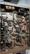
Some questions: Is your 8b set up for triode mode? Since the bias rectifier was selenium can we assume that this amplifier is as it left the factory? Have you checked R19A and B? Current enough to wipe out R20 flows through the shared cathode resistor too. Can we see pictures of "under the hood"?
 
Some questions: Is your 8b set up for triode mode? Since the bias rectifier was selenium can we assume that this amplifier is as it left the factory? Have you checked R19A and B? Current enough to wipe out R20 flows through the shared cathode resistor too. Can we see pictures of "under the hood"?
It is not set up for triode mode. I have check R19A & R19B & R20. They should be OK.
 

Attachments

  • 20250611_120147.jpg
    20250611_120147.jpg
    151.5 KB · Views: 58
You also indicated that you needed to replace one 100 ohm screen grid resistor. These tend to get damaged when tubes run away. I would double check all of these for tolerance and give them a little push with pencil or plastic tool. Sometimes they get really brittle after being stressed and just snap in half.
I have checked the other 100 ohm resistors, they should be OK.
 
So far it is sounding like the issue is not isolated to a single socket or a single suspect tube. The next thing that I am thinking is that the negative bias supply dual capacitor may be going bad and there is ripple on the tube grids. Do you have a way to test capacitors?

You could also try measuring AC voltage at the output of the dual cap C17. If its more than a few hundred mV it may indicate elevated ripple.

Just as a side note, if all of your tubes are set to the bias line, according to the grid voltages that you measured your tubes are pretty badly mismatched. This should not contribute to red plating.
I use the FNIRST Intelligent Bridge Tweezers LCR-ST1 to check the C17, it shows that one is 19.65uf D:0.2, the other is 20.30uf D: 0.1
I use the Multi Meter to measure the AC voltage of the C17 as below:

1. C17 Positive leg (R35 Ground side) with Black probe to C17 Coil side: 0v AC
2. C17 Positive leg (R35 Ground side) with Black probe to Diode Negative side (other side of R35): 25v AC

3. C17 Positive leg (R35 Ground side) with Red probe to C17 Coil side: 105v AC
4. C17 Positive leg (R35 Ground side) with Red probe to Diode Negative side (other side of R35): 0v AC

5. C17 Negative leg with Black probe to Diode Negative side with Red probe: 140v AC
6. C17 Negative leg with Red probe to Diode Negative side with Black probe: 0v AC

I have two sets of EL34, one set is newly match while the other set is old.
 
That big electrolytic cap that is mounted horizontally via the snap in clamps (close to the power transformer) looks terrible! It also looks like it may be cracked at the base (?).
 
That big electrolytic cap that is mounted horizontally via the snap in clamps (close to the power transformer) looks terrible! It also looks like it may be cracked at the base (?).
That cap that looks "terrible", C19, is in it's original vinyl insulating sleeve. Those sleeves get that way after 60+ years. It is one half of a voltage doubler, the other, C20, is mounted on top by the bias meter along with C16. C17, the dual bias capacitor has an insulation sleeve on it too and it looks old as do C3A,B.
I could go on further but what is apparent to someone who has serviced these is that other from the new 100 ohm resistor, the amplifier is original. Great for a collector who wants originality but doesn't intend to ever use it. It is time for a restoration.
 
That big electrolytic cap that is mounted horizontally via the snap in clamps (close to the power transformer) looks terrible! It also looks like it may be cracked at the base (?).
You are right. I bought it years ago from ebay and seldom use it until recently. When the tube turned red I open the bottom plate and find these terrible capacitors. I am going to restore it after fixing this issue. However, it sound wonderful before cracked down.
 
That cap that looks "terrible", C19, is in it's original vinyl insulating sleeve. Those sleeves get that way after 60+ years. It is one half of a voltage doubler, the other, C20, is mounted on top by the bias meter along with C16. C17, the dual bias capacitor has an insulation sleeve on it too and it looks old as do C3A,B.
I could go on further but what is apparent to someone who has serviced these is that other from the new 100 ohm resistor, the amplifier is original. Great for a collector who wants originality but doesn't intend to ever use it. It is time for a restoration.
You are right. I bought it years ago from ebay and seldom use it until recently. When the tube turned red I open the bottom plate and find these terrible capacitors. I am going to restore it after fixing this issue. However, it sound wonderful before cracked down.
 
You are right. I bought it years ago from ebay and seldom use it until recently. When the tube turned red I open the bottom plate and find these terrible capacitors. I am going to restore it after fixing this issue. However, it sound wonderful before cracked down.
Restoring it will fix "the issue".
 
Back
Top Bottom