• The move to the new server is done. There are some software and database maintenance updates in process. This has us passing the hat around to help out. We appreciate any donations. Seriously, even a dollar helps. The payment page may be found here - https://www.audiokarma.org/support.html

Marantz Model 140 – Single Filter Capacitor Revision? Both Channels Failed Simultaneously

jammosherJAM

New Member
Hi everyone,


I'm hoping someone here has run across this before because I'm starting to think my Model 140 is a production revision that doesn't match the commonly available service manual.


I've been troubleshooting it methodically and trying to avoid replacing parts without evidence, but I've reached the point where I think I need someone with more Marantz experience to tell me whether I'm missing something obvious.


The amplifier​


  • Marantz Model 140
  • Serial number: AO140/25/220240V 50/60Hz 300W (see attached photos)
  • Manufactured in Japan

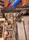
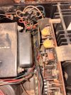
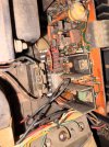
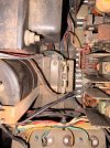
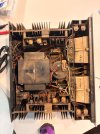
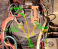
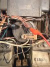
The first thing that caught my attention is that the power supply doesn't match the service manual. My amplifier has one large multi-section filter capacitor, not the layout shown in the manual. The amplifier boards and wiring also differ in several places, which makes me think this may be an undocumented production revision rather than a modified amplifier.


Failure​


The amplifier had been working normally.


I had a Denon AVR connected to the inputs with no speakers connected. The front-panel meters were responding normally. The input level controls were turned down.


Then, without warning:


  • Both channels developed a loud 60 Hz hum.
  • Both VU meters froze around -5 dB.
  • No audio output after that.
  • The behavior is identical on both channels.

Because both channels failed at exactly the same time, I've been focusing on something common to both channels rather than assuming two independent failures.


Measurements so far​


Bridge rectifier:


    • to - : 77.8 VDC
    • to each AC terminal: 31.6 VAC
    • to each AC terminal: approximately 46 VAC

Main filter capacitor wiring:


  • Tan to Red: 77.8 VDC
  • Tan to Black: 31.7 VDC
  • Black to Red: 46 VDC

Speaker outputs:


  • Left: approximately 0 VDC
  • Right: approximately 0 VDC

So at this point it appears:


  • Transformer is alive.
  • Bridge rectifier is functioning.
  • Main supply voltage exists.
  • The outputs are not sitting on a supply rail.

Where I'm stuck​


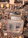
I started trying to access the solder side of one amplifier board, but it appears the board is mechanically captured by the heatsink/output transistor assembly and doesn't simply lift out after removing the mounting screws. Rather than force anything, I stopped.


My questions​


  1. Does anyone recognize this as a known Model 140 revision?
  2. Is there a service manual or supplement that matches the single multi-section filter capacitor version?
  3. Given the simultaneous failure of both channels and the measurements above, where would you investigate next?

I've attached photos of the amplifier, the power supply, and the amplifier board. If there are additional voltages or continuity checks that would be useful, I'm happy to take them.


I'd really appreciate any insight. I'm trying to understand why it failed rather than blindly replacing parts, and I'd like to preserve the amplifier as much as possible during the repair.


Thanks!
 
  • Like
Reactions: mbz
Register to hide this ad
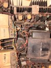
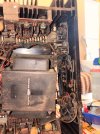
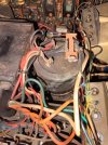
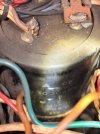
Photos of the guts for reference
 

Attachments

  • IMG_7658.jpeg
    IMG_7658.jpeg
    170.2 KB · Views: 33
  • IMG_7660.jpeg
    IMG_7660.jpeg
    165.6 KB · Views: 29
  • IMG_7661.jpeg
    IMG_7661.jpeg
    143.9 KB · Views: 29
  • IMG_7695.jpeg
    IMG_7695.jpeg
    171.3 KB · Views: 40
  • IMG_7697.jpeg
    IMG_7697.jpeg
    113.5 KB · Views: 32
  • IMG_7706.jpeg
    IMG_7706.jpeg
    135.5 KB · Views: 28
  • IMG_7709.jpeg
    IMG_7709.jpeg
    148.8 KB · Views: 27
Speaker outputs:


  • Left: approximately 0 VDC
  • Right: approximately 0 VDC
If there was a dc offset issue then the relay would be open so no contact between spkr outs and power amp board. Need to measure before the relay, eg, JN06(L) and JN07(R)
 
Measured JN06 and JN07 to chassis ground with the amp powered on through the DBT. Both are essentially 0 VDC. The relay clicks normally every time the amp is powered on. The symptom remains: loud hum in both channels, both VU meters stuck around −5 dB, and no audio.
 
Last edited:
  • Like
Reactions: mbz
Both channels affected would normally point to something in common like the power supply however the psu is very basic, ie, rectified, smoothing caps and the odd zener. Also would expect the "hum" to be 120Hz rather than 60Hz.

Can you confirm the hum is 60Hz or rectified 120Hz, measure rather than "it sounds like..." A scope would be handy however there are phone aps like spectroid and others or pc freeware like audacity, record and upload...

Assuming it's 60Hz then need to test all GND connections.
With unit powered off/unplugged measure resistance between main cap terminal with black wires and chassis.
Repeat for main cap terminal (black) and other GND points, refer to sm, eg test at J709 and also the L, R input RCA's GND (outer) connection, all measured back to main caps. 0.5ohms or above should be investigated, need to subtract probe/leed resistance, ie short probes together, what does MM read, subtract this off the other GND measurements.
 
I'm hoping someone here has run across this before because I'm starting to think my Model 140 is a production revision that doesn't match the commonly available service manual.
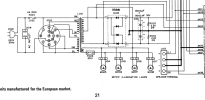
From your photos, it looks like it matches the European, multi-voltage power supply like in the SM?
  • Main filter cap is dual 13,000uF (same as SM)
  • Multi-voltage selector on rear panel (same as SM)
  • Fuse holder is either F003/F004 @ 4A (same as SM)

1785509047643.png
Main filter capacitor wiring:
  • Tan to Red: 77.8 VDC
  • Tan to Black: 31.7 VDC
  • Black to Red: 46 VDC
Your main cap voltage measurements are not right. C001 should be a dual 13,000uF capacitor (two capacitors in one package as shown in the schematic above).
From the schematic, it looks like you should have 55VDC on each of the power leads (lead to ground).
One voltage should be positive, with respect to ground. The other voltage should be negative to ground.
You did not note the polarity of your voltage measurements above so I can't tell if it is correct, but still the voltage is low.

1785510748067.png
Bridge rectifier:
  • to - : 77.8 VDC
  • to each AC terminal: 31.6 VAC
  • to each AC terminal: approximately 46 VAC
To me, it is not clear what you are measuring on the bridge rectifier. (H005)
  • I'm not sure what you mean by "to -"
  • You should measure ACV from ~ terminal to the other ~ terminal
  • You should then measure DCV from + terminal to ground, then - terminal to ground (black DMM lead on chassis ground)
  • It looks like your AC terminal measurements are the same as the cap terminal measurements.
CAUTION: Before making any capacitor measurements on the main filter cap, discharge each terminal to ground using a 100 Ohm resistor because the large cap (13,000uF) can still hold a charge that will zap you if you touch it.

Do you have a capacitor tester or a DMM that can read capacitance (up to 13,000uF)?
I can't tell if it's the cap or bridge rectifier that is bad.
 
Thanks for pointing me in this direction. I finally managed to get some consistent readings.

Everyone bear with me, I’m all new to this

I also took a recording of the hum and analyzed it. It appears to be predominantly 60 Hz, so I figured it was worth following up on the ground checks you suggested.


With the amplifier unplugged, I measured from the main filter capacitor terminal with the black wires:


  • Chassis: 0.3 Ω
  • Left RCA outer shell: 0.3 Ω
  • Right RCA outer shell: 0.0–0.1 Ω

The relay still clicks a few seconds after power-up every time. I also measured JN06 and JN07 to chassis ground with the amplifier powered on, and both were essentially 0 VDC.


The symptoms are still unchanged: both channels produce a loud 60 Hz hum, the gain controls have no effect on the hum, and the VU meters sit around -5 dB and don’t respond when I feed the amplifier a signal.


Based on these measurements, it seems like the main ground connections are okay. Where would you recommend I go next?
 
I remeasured the power supply using chassis ground as the reference.


AC across the bridge rectifier (~ to ~): 69.8 VAC


DC to chassis:


  • Red: +45.5 V
  • Black: 0.0 V
  • Tan: −30.8 V

Ground continuity from the main filter cap to chassis measured about 0.3 Ω, and the RCA grounds measured 0.0–0.1 Ω after subtracting lead resistance.


Based on these readings it looks like the transformer is supplying AC, but the DC rails are unbalanced. Does this point more toward the bridge rectifier, the dual filter capacitor, or should I be looking for a load on one rail from the amplifier board?
 
DC to chassis:
  • Red: +45.5 V
  • Black: 0.0 V
  • Tan: −30.8 V
What are the AC voltage measurements for these same locations? This may tell if it's the caps or rectifier.
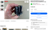
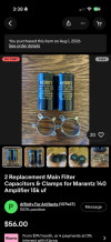
Those voltages are both low, it looks like the schematic shows +/-55V. I would start with replacing the capacitor... but I don't think that you will find a dual 13,000 uF capacitor so you may need to connect up two separate caps.
You might have enough room to install one of these?
1785517353582.png

Also, one of your photos shows a fuse is missing. Did you remove it?
 
Last edited:
Sorry, I removed the fuse earlier in testing.

I rechecked the AC measurements with the amp powered on and got approximately:


  • Red: 0.4 VAC
  • Black: 0.4 VAC
  • Tan: 9.0 VAC

The amplifier still has the same steady hum in both channels with only speakers connected, and the volume control has no effect on the hum.
 
Last edited:
Also, I wasn’t using the most reliable chassis ground point, so some of my previous measurements might not have been accurate. I feel more confident now
 
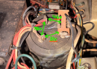
Just to verify. Is this how you measured your voltages?
Why is one of them not negative? You should put you meter black lead on the black wire and measure the red and white. One should be -.
The black lead should be the same as chassis ground??
(Note: my ground symbol is not on the cap, just drawn there for convenience. Pick a chassis or screw tied to the chassis)

Turn off power, unplug, and measure resistance from the black lead to chassis ground. It should be 0 Ohms.

1785517997067.png
 
I rechecked the measurements using the same chassis screw as the reference for all three readings.


  • Red (+): +46 VDC
  • White (−): −32 VDC
  • Black (common): 0.0 VDC

The black/common terminal measures the same as chassis ground.
 
If black has 0VDC, (did you check the resistance from the black to chassis with power off) presumably it is tied to chassis ground. Then why do you measure 9VAC with respect to chassis ground?
 
I think I sorted out the confusion from my earlier measurements.


I found that my chassis ground reference wasn’t very reliable at first, so I rechecked everything using the same chassis screw for all measurements.


Power ON (DC):


  • Red: +46.0 VDC
  • White: −32.1 VDC
  • Black/Common: 0.0 VDC

I then switched to AC volts and, using the same chassis screw as the reference, measured:


  • Red: 9.5 VAC
  • White: 9.9 VAC
  • Black/Common: 0.4 VAC

Since the black/common terminal measures 0 VDC to chassis, I agree the AC readings don’t seem to make sense. My meter is a basic Cen-Tech CM300, so it’s possible I’m not measuring ripple correctly or the meter isn’t suitable for this measurement.


The amplifier still has the same steady hum in both channels with only speakers connected, and the volume control has no effect.


What would you like me to measure next?
 
I rechecked the ground connection with the amplifier powered off. Resistance from the capacitor common (black terminal) to chassis is 0.061 Ω, so it appears the common terminal is indeed tied directly to chassis ground. My earlier AC reading from the common terminal to chassis was due to a poor probe connection. Rechecking with a solid chassis ground point gives essentially no voltage difference.
 
I then switched to AC volts and, using the same chassis screw as the reference, measured:
  • Red: 9.5 VAC
  • White: 9.9 VAC
  • Black/Common: 0.4 VAC
That's better... my guess is that the audio hum that you are hearing is due to the high AC voltage on the DC power lines. 10V on 55V is too high. It should probably be in the millivolt range of AC. It looks like you should replace the dual 13,000uF capacitor. I don't think ;you can find a dual cap, you might need to use the one that I found on ebay. Affinity for Artifacts is also an AK member.
 
I have a single capacitor version and was sent dual caps. How do I install correctly??
 

Attachments

  • IMG_7980.jpeg
    IMG_7980.jpeg
    152.3 KB · Views: 18
  • IMG_7988.png
    IMG_7988.png
    312.7 KB · Views: 17
Back
Top Bottom