• The move to the new server is done. There are some software and database maintenance updates in process. This has us passing the hat around to help out. We appreciate any donations. Seriously, even a dollar helps. The payment page may be found here - https://www.audiokarma.org/support.html

Marantz Model 140 – Single Filter Capacitor Revision? Both Channels Failed Simultaneously

I'm not sure what you ordered, but this is what I suggested in an earlier post?
It has a PC board to mount the two caps + two caps for $30.
The two caps that you have will work if they can physically fit into the space of your one cap. You just need to wire them correctly.
1786142808541.png
 
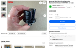
I messaged the eBay seller and they told me that the two individual caps should be compatible. Can someone draw or describe exactly where each original wire goes on two individual capacitors? I already have two 15,000 µF Kemet capacitors installed and just need the wiring
 
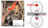
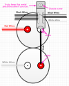
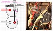
Here is how to connect the two caps.
  1. Make sure you identify which terminal of the new caps is - and +. It is either marked with a "-" on the side of the cap or "+"/"-" stamped on the solder terminals.
  2. Red wires to the + of one cap
  3. White wires to the - of the other cap
  4. Solder that whole metal strip between the - side of the top cap and the + side of the bottom cap (as shown in the drawing). That is your Common terminal.
  5. It looks like that bar with all of the wires is some type of metal. You can keep the wires soldered to it, but you need to clean the metal where you will solder it to the new cap terminals. Clean it with isopropyl alcohol and apply some solder flux to it if you have some. It will help the solder to flow nicely.
  6. I can't tell from you photo where the small red wire goes to and the large white wire. You need to look at it and connect it the same place as the original. If it is connected to the metal bar then leave it connected.
  7. Just think of your two new caps as one dual cap.
  8. MAKE SURE TO CONNECT THE - TERMINAL OF THE TOP CAP TO THE + OF THE BOTTOM CAP (not - to -, or + to +) Got It!
Ask questions if you don't understand what I wrote.
1786146256636.png
1786147067032.png
 
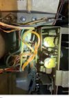
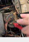
Thanks! I understand the two-cap wiring now. One last question before I solder: can you confirm what the small red wire and the large white wire in my original photos are supposed to connect to? Are both of those part of the same connections shown in your diagram, or does either one go somewhere else? I want to make sure I reproduce the original wiring exactly.
 
I don't know where they go to. Connect them to the same as the original terminal: +, -, or common.
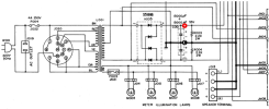
If you can tell me where the other end of each goes to I can look on the schematic above.
 
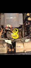
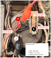
Would this photo help identify the two wires? I labeled the relevant terminals/wires A, B, C, and D. Can you tell me which of these correspond to the original +, −, and common terminals of the dual capacitor, and specifically where the small red and large white wires should go on the two replacement capacitors?

IMG_7989.jpeg
 
Can you tell me which of these correspond to the original +, −, and common terminals of the dual capacitor, and specifically where the small red and large white wires should go on the two replacement capacitors?
Your other photo was better because you wrote all over the wires that I would want to look at with yellow circles and AB.
  • Just connect the wires up exactly the same way as the original wiring.
  • You shouldn't need to unsolder any of the wires from that metal plate. Just unsolder the plate from the old cap terminal and solder it to the new terminals as I showed in my diagram several posts ago.
  • It looks like the small red wire and large white wire are soldered to the metal plate. If that's where they are just keep them there.
The first thing that you need to do is cut-off those black cable ties so you can separate the wires and see them all.
  • Whatever is connected to the old + terminal connect to the new + terminal.
  • Whatever is connected to the old - terminal connect to the new - terminal.
  • Whatever is connected to the common (C) terminal connect to the same metal strip except instead of it being soldered to one cap terminal, it will be connected to two terminals as I showed in my diagram above.
So I have a question... you said that you already installed the two capacitors. How can you do this without unsoldering all of these wires?
By the way, where you have the red and black alligator clips won't measure a meaningful voltage. The black lead needs to be connected to the "C" terminal and the red lead to either the + or - terminal.

CAUTION!!!: If I haven't already said this, I am providing a caution now. :yikes: The capacitor will hold a voltage for an indefinite time, even with the power switched off and unplugged. You may have 45VDC on the terminals which could give you quite a shock if you touch them, not to mention potential for damaging other components.

When working around this capacitor make sure you do the following:
  1. Unplug the amplifier from the wall AC socket.
  2. Discharge both the + and - terminal to ground through a 100 Ohm 1 or 2W resistor.
  3. Check for voltage after discharging with your multimeter to make sure there is no voltage left in the cap.

1786163234893.png
 
Last edited:
Here is a better photo of someone else's Model 140. Maybe you can use this as a reference to what yours should look like.
From his photo, it looks like that plate is also connected to chassis ground so you will need to figure out how to connect it to your new caps.
Maybe solder it onto one terminal then solder a heavy wire from the common terminal on one cap to the other.

1786167337974.png
 
That reference pic helps a lot. Just want to make sure I don’t screw this up before I start moving wires around


On the original setup, how exactly should I connect that metal plate/strip to the two new caps and chassis ground?


And should I run a heavier jumper between the common terminals of the two new caps?


If you could mark up my original pic and show me where those connections should go, that would probably make this a lot easier for me.
 
Maybe see if the caps will fit something like this where you can attach the ground strap to one cap terminal. (the cap height may be different).
  • Keep the bracket screwed to the chassis as is
  • Position the capacitors so that you can solder the metal conductor piece to the - terminal.
  • Use a heavy wire to connect the - terminal from the top cap to the + terminal of the bottom cap and solder both sides to the terminals.
  • Connect all of the red wires to the top + terminal
  • Connect all of the white wires to the bottom - terminal.
  • In the other photo, I only see the one thick white wire connected to the strip with the black wires. I don't see the thin red wire attached to it. Where does the thin red wire go to on yours?
  • You are on your own to make sure that it is wired correctly (as the original wiring was) since I cannot check your work 100%.
1786169743254.png
 
I restored two of these amps. In one I moddified the existing ground strap and used screw top capacitors, and the other I used a piece of copper plate, drilled holes it it for the cap leads and wiring, then ran a wire for the ground.
 
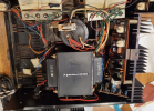
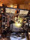
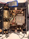
Thanks, I took some more pictures of my actual amp to try to make this easier to figure out. The first one shows the overall layout and the others are closer shots of the wiring around the power supply/capacitor area.


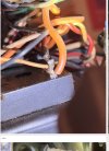
I’m still trying to figure out exactly where the original wires go before I install the new caps. Does this give you enough to tell me how you think I should wire them? I’m also trying to trace that smaller red/orange wire you mentioned.
 

Attachments

  • Photo_3_-_Orange-red_wire_close-up.jpg
    Photo_3_-_Orange-red_wire_close-up.jpg
    188.4 KB · Views: 9
  • Photo_2_-_Wiring-control_area.jpg
    Photo_2_-_Wiring-control_area.jpg
    168.8 KB · Views: 8
  • Photo_4_-_Transformer-capacitor_area.jpg
    Photo_4_-_Transformer-capacitor_area.jpg
    125.8 KB · Views: 8
  • Photo_5_-_Additional_wiring-terminal_area.jpg
    Photo_5_-_Additional_wiring-terminal_area.jpg
    178.6 KB · Views: 10
  • IMG_8064.jpeg
    IMG_8064.jpeg
    246.8 KB · Views: 11
  • IMG_8017.jpeg
    IMG_8017.jpeg
    304.5 KB · Views: 15
I restored two of these amps. In one I moddified the existing ground strap and used screw top capacitors, and the other I used a piece of copper plate, drilled holes it it for the cap leads and wiring, then ran a wire for the ground.
That’s really helpful, thank you! Mine still has the original ground strap, and I’m trying to figure out exactly how everything was connected before I put the new caps in.


I took a few more pictures of mine. Since you’ve actually restored two of these, would you mind taking a look and seeing if you can tell me where the original wires should go? I’m especially trying to figure out the smaller red/orange wire in these pictures. I just don’t want to guess and end up wiring something wrong.
 
That's not right. Just compare my picture to your photo and wire it the same way.
  1. All red wires go to the + terminal on the top cap (I am assuming that those red wires are connected to the + terminal of that cap?)
  2. All white wires go to the - terminal on the other cap (it looks like you have it connected to the same cap as the red wires - not correct. They need to go to the other cap)
  3. Connect the black wires with the metal strip onto the - terminal of the top cap
  4. Connect the metal strip with a wire to the positive terminal of the other cap.
It's VERY simple. Do you have a problem following my diagram?
You just need to make sure that you have the + and - terminals of the two caps connected correctly.
You should rotate the caps so the terminals line up like my diagram. Yours are in a random position???
The photos are too blurry to see any detail to tell what the orientation of each cap is.
When you take a photo, mark which terminal is + and which is - on the top of the cap so I can see it.

1786219334976.png
 
That's not right. Just compare my picture to your photo and wire it the same way.
  1. All red wires go to the + terminal on the top cap (I am assuming that those red wires are connected to the + terminal of that cap?)
  2. All white wires go to the - terminal on the other cap (it looks like you have it connected to the same cap as the red wires - not correct. They need to go to the other cap)
  3. Connect the black wires with the metal strip onto the - terminal of the top cap
  4. Connect the metal strip with a wire to the positive terminal of the other cap.
It's VERY simple. Do you have a problem following my diagram?
You just need to make sure that you have the + and - terminals of the two caps connected correctly.
You should rotate the caps so the terminals line up like my diagram. Yours are in a random position???
The photos are too blurry to see any detail to tell what the orientation of each cap is.
When you take a photo, mark which terminal is + and which is - on the top of the cap so I can see it.

View attachment 3815126

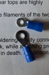
Ya, just follow the picture he posted. Ive also soldered crimp on ring conectors to caps to make attaching multiple wires to the leads like the one in the picture below. There are enough boles in the bottom of the chassis to attach and arrange cap clamps also.
 

Attachments

  • 20260808_134051.jpg
    20260808_134051.jpg
    84 KB · Views: 1
That's not right. Just compare my picture to your photo and wire it the same way.
  1. All red wires go to the + terminal on the top cap (I am assuming that those red wires are connected to the + terminal of that cap?)
  2. All white wires go to the - terminal on the other cap (it looks like you have it connected to the same cap as the red wires - not correct. They need to go to the other cap)
  3. Connect the black wires with the metal strip onto the - terminal of the top cap
  4. Connect the metal strip with a wire to the positive terminal of the other cap.
It's VERY simple. Do you have a problem following my diagram?
You just need to make sure that you have the + and - terminals of the two caps connected correctly.
You should rotate the caps so the terminals line up like my diagram. Yours are in a random position???
The photos are too blurry to see any detail to tell what the orientation of each cap is.
When you take a photo, mark which terminal is + and which is - on the top of the cap so I can see it.

View attachment 3815126
In your drawing that's pretty much how I used the existing ground strap in the one amp that I used screw tops. I notched the end of the plate to fit the screw on the cap, and added a short jumper wire for the other cap's ground screw.
It workwd out well.
 
Back
Top Bottom