Ryan Scruggs
New Member
Hi, all!
I have previously posted about some issues I have been having with my Marantz SD 9000. I have replaced the notoriously bad optocouplers, and all belts and idler tires.
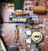
What I neglected to notice were the burnt out resistors on the PK21 board of the machine. I purchased and replaced these resistors, with the exception of one. Here is a picture of the section of the board in question before I attempted the replacement. The R516 resistor (inside blue box), despite my best efforts to photograph the board before I de-soldered the resistors, has been giving me problems.
As I have said, I have replaced (successfully) the remaining burnt out resistors, but now I cannot seem to figure out the proper connections that need to be made for the R516 resistor.
To aid in a solution, here is the schematic of the PK21 board, with the R516 resistor in the blue square:
If someone could clarify, in layman terms, the correct orientation and connections that need to be made to complete the restoration of the PK21 board, I would be eternally grateful! I also have a wire that has become un-soldered, and I am unsure of its origin, but that will be an issue for another forum post!
Thanks again!
I have previously posted about some issues I have been having with my Marantz SD 9000. I have replaced the notoriously bad optocouplers, and all belts and idler tires.
What I neglected to notice were the burnt out resistors on the PK21 board of the machine. I purchased and replaced these resistors, with the exception of one. Here is a picture of the section of the board in question before I attempted the replacement. The R516 resistor (inside blue box), despite my best efforts to photograph the board before I de-soldered the resistors, has been giving me problems.
As I have said, I have replaced (successfully) the remaining burnt out resistors, but now I cannot seem to figure out the proper connections that need to be made for the R516 resistor.
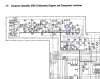
To aid in a solution, here is the schematic of the PK21 board, with the R516 resistor in the blue square:
If someone could clarify, in layman terms, the correct orientation and connections that need to be made to complete the restoration of the PK21 board, I would be eternally grateful! I also have a wire that has become un-soldered, and I am unsure of its origin, but that will be an issue for another forum post!
Thanks again!