

You are using an out of date browser. It may not display this or other websites correctly.
You should upgrade or use an alternative browser.
You should upgrade or use an alternative browser.
Marantz Service Manual error thread
- Thread starter Jailtime
- Start date


hedroom
Active Member
The Marantz 3200 Schematic shows C401 & C402 (input side of phono board) as 1uF/50V. Parts list and actual component is 2.2uf/35V.
I've also attached a PNG image of the schematic with all of the corrections from this thread (see below). Image also includes color coded audio paths some might find helpful
Cheers,
Wade
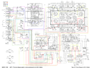
I've also attached a PNG image of the schematic with all of the corrections from this thread (see below). Image also includes color coded audio paths some might find helpful
Cheers,
Wade
Last edited:

In this thread: https://audiokarma.org/forums/index...ifier-board-bias-issue.1072060/#post-17438676
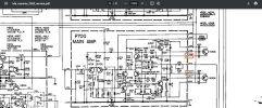
@dankik noticed biasing instructions for a Marantz 2252 are incorrect. The corrected pins are as follows:


@dankik noticed biasing instructions for a Marantz 2252 are incorrect. The corrected pins are as follows:
Last edited:



Marantz Model 150 Tuner:Help us out! If you've run across anything that's wrong in the Marantz service manuals, post it!
My Serial # 1671
The PDF schematic of the power supply Connector JO11 Pin 15 Shows a voltage of 33 Volts DC. This feeds the Output rear section of the tuner. In fact the Voltage is really Around 25 Volts when on and measured. When this lead is disconnected from the terminal it will show somewhere around 48 Volts DC and when reconnected it read s again Around 25 Volts.
Since I have a new version in serial # I have checked the same terminal. It also reads around 25 Volts DC. So I would assume this is a Mistake on the Schematic reading 33 Volts DC.


https://akdatabase.com/AKview/thumbnails.php?album=1&page=5
@dustidean, Schematic, Owner's Manual, Hi-Res schematic, Parts List are here in the AK Database.

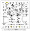
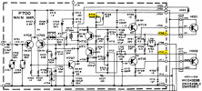
@dustidean, Schematic, Owner's Manual, Hi-Res schematic, Parts List are here in the AK Database.
Last edited:

jd3rdcoast
Super Member
On my bench a Quad 4300 S/N 4989, on PE01 Buffer & Preamplifier board YD2892005-2 the VD1212 dual diodes HE21-HE24 are silkscreened as RE21-RE24 and with resistor symbols. The VD1212 dual diodes are installed correctly so pay attention to the layout. If unsure, the board layout in SM is correct with proper part numbers and symbols. Replace with two 1N4148 diodes soldered together. -->|-->|--

bluehills5
Active Member
This link is now broken but here is a working link. Note the online version of MS Word may default to Dark Mode. Go to View>switch background to view as normal. Feel free to download and use as you wish.Although I've posted this before, I scanned in a copy of the 2270 manual and converted it all to readable text using OCR software and used the best circuit diagram scans I could find and made them into Word & PDF docs. I've also corrected some (but not all) the errors that were found in this post. Using this you should be able to make a "correct" 2270 manual.Here is the link..
https://1drv.ms/f/s!AulYHAx4JToPaA0ARopgvLMJHmM
model 2270 Updated.docx
Marantz 2226B bias adjustment.
Instructions say to place the meter between resistors R757 & R759, then for the other channel between R758 & R760.
If the leads were placed there they would be in the same spot. They mean across the resistors, at the output transistor emitters.

Instructions say to place the meter between resistors R757 & R759, then for the other channel between R758 & R760.
If the leads were placed there they would be in the same spot. They mean across the resistors, at the output transistor emitters.
Hi, I am restoring a Marantz 2210, and can’t find the schematic, do
You have a copy?
Thanks
You have a copy?
Thanks
@Mcintosh N, are you looking for a schematic for a 2210 receiver, 2110 tuner, or 2010 receiver as @icko30 posted a link to?
Last edited:
Thanks for your answer
I broke the volume slider balance pot and trying to replace it another one that fit from a sansui, same value but different wiring.
It is the 2010 Marantz.
Thanks again
I broke the volume slider balance pot and trying to replace it another one that fit from a sansui, same value but different wiring.
It is the 2010 Marantz.
Thanks again

Lumpazius
New Member
...and another gross mistake on Board P700
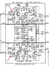
In the circuit diagram of the 2330B (also the 2285B and possibly others with this main amp board), there is an error regarding Q723 and Q753. The circuit diagram is missing a connection point directly after the base terminal of both transistors! In the original circuit diagram, it looks as if Q723 and Q753 are only connected to the 220 ohm resistor. However, the connection also goes to R734, R736, and C718 (in the Q753, to R780, R784, R786, and C738). Attached are two pictures that show what I mean.
The original

...corrected
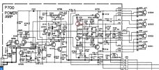
In the circuit diagram of the 2330B (also the 2285B and possibly others with this main amp board), there is an error regarding Q723 and Q753. The circuit diagram is missing a connection point directly after the base terminal of both transistors! In the original circuit diagram, it looks as if Q723 and Q753 are only connected to the 220 ohm resistor. However, the connection also goes to R734, R736, and C718 (in the Q753, to R780, R784, R786, and C738). Attached are two pictures that show what I mean.
The original
...corrected

d.s.f.
New Member
Similar to other mistakes mentioned here in the past, the 2240B SM incorrectly lists capacitors CE21 and CE22 as 33uF when they should be 3.3uF. Similarly the copy of the manual I have saved on my phone also lists CE05 and CE06 as 47uF when they should be 4.7uF but I just noticed that the copy I have here on my PC lists the correct values, so maybe there's an even later revision that corrects both.