• The move to the new server is done. There are some software and database maintenance updates in process. This has us passing the hat around to help out. We appreciate any donations. Seriously, even a dollar helps. The payment page may be found here - https://www.audiokarma.org/support.html

Marantz Service Manual error thread

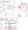
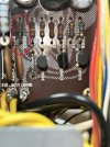
Looking at a Marantz 2330, and finding some puzzling differences between P700 in person vs the schematic.

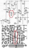
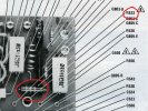
P700 has screening and holes for Q722 & Q723 and both appear on the board diagram, but neither is installed on these 2330 P700. Q722 is in the schematic, but Q723 is not.

Q728 is on the real board and diagram, but not the schematic.
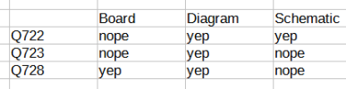
2330 parts mystery.png

Were there any known revisions? Service bulletins? Are there any documents that might help clear this up?

I've consulted (digital, not paper) service manual, US and Euro schematics. None tell any different story. I've googled quite a bit.

Finally, the parts list in the service manual agrees with the machine here: no listing for Q722, 723, but Q728 is present.

-----------
Edit:

Further time with the machine makes it look like the schematic should have said Q728 where it says Q722, that Q728 is doing what the schem says Q722 does. Hope this saves somebody else some time...


A second error: R718 and R719 are in the schematic as 33ohm, but are in the amp and parts list 150ohm resistors.
 
Last edited:
Marantz Model 25:
Main amp board parts list lists C505-C508 as 22uF/35V electrolytic, but the schematic and board have 0.03uF ceramic caps. That's quite a difference...
 
Marantz 2220b/2225 manual list R129 as 27k on the P100 board. The correct one is a carbon comp 1/2 watt 2.1K ohm. Not really a big deal for most but I replace all carbon comps.
 
Marantz 2220 schematic error:

On the P300 board, the power comes in at J302 and hits R355 (220 ohms), but there is a "dot" missing to connect to the first horizontal line after the line exiting R355 goes upwards. That horizontal line has the local filter cap C306 on it and is the power connection for the first three stages, H310-303.
 
Marantz 250M Capacitor C303: on schematic shows "22/6.3" but on the Parts List shows "CAPACITOR, ELECTROLYTIC, 22 MFD, 63V". The capacitor that I removed from the Relay Board was 22 MFD, 63V. I'm reasonably sure that the cap removed was original.

1707013108060.png
 

Attachments

  • 1707012674962.png
    1707012674962.png
    107.5 KB · Views: 6
Searched for this error and didn't find it. The silkscreen for the QN02 diode on the PN00 relay board is flipped. IMG_1667.JPG
In addition, in the schematic for that board, there are two QN05s. The bottom one should be QN03, not QN05.
 
Marantz 250M: two additional incorrect schematic notes...

  1. C502 - CAPACITOR, ELECTROLYTIC, TA, 10 MFD, 20V. The polarity incorrectly orientated on the main schematic (page 13) but is correct on the "printed circuit page" (page 23). The negative end of the cap should be connected to the collector of Q518 and the emitter of Q519.
    Both of my boards have the C502 cap installed as per the "printed circuit page" and I believe that they were original equipment.
    C502 Snip.jpg


  2. R553 - RESISTOR, C-C, 5.6 ± 5%,1W is marked as R533 on the "component side page" (page 22) but is correct on the "printed circuit page" (page 23).
    R553 Snip.jpg
Cheers,

Wade
 
Can anyone please send me a copy of the Marantz 4400 service manual and other docs, that are clear to read (good resolution)? Thanks in advance!

Hifi Engine is not accepting noobies...
 
These look great. Thank you, @dankik.

Although after working on a SX780 Pioneer, the schematics for the 4400 look like they could be for the space shuttle. Oh boy.
 
On page 16 of the 3250B Manual, there is an error in the description of the QE08 transistor. It should read: "2SA941" instead "2SA041".
 

Attachments

  • Errata_1.png
    Errata_1.png
    109.2 KB · Views: 9
Marantz 2252B, CE23 and CE24 should be 1uF/50V, +/-20% Non-Polarized electrolytic capacitors as marked on the schematic, but not in the parts list.
Also, C721 on the board layout shows incorrect capacitor polarity (+), board silkscreen is correct orientation (opposite from layout).

In addition, C722 has the same error dankik pointed out on the layout as C721 but the silkscreen is marked correctly.

Be aware Q718 is listed twice on the board layout. The listing nearest the power supply section (left of sheet) should be labeled Q715.

And, C738 is mislabeled on the schematic as C783. The etching is correct, however.
 
Last edited:
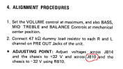
On page 2 of the 3650 preamplifier service manual, the alignment procedure incorrectly describes the wrong pin to use for measuring -32V. Instead of pin J810, one should use any of these pins: J816, J817, or J818 to measure voltage drop of -32V between it and chassis ground. J810 is a ground pin and you should never see any voltage drop across this pin and chassis ground.
 

Attachments

  • Errata_1_Alignment.png
    Errata_1_Alignment.png
    55.3 KB · Views: 7
Marantz 2252B service manual errors (hifi engine version)
A few of these errors came from the Audiokarma service manual error thread; sorry for including without credit. I discovered many more. I decided to just put all the ones I know of into one post. I have also updated many pages; I may look into uploading those here and elsewhere as well.

P200 schematic: (correct on pp. 25-26 as well)
P100 schematic: (correct on pp. 25-26 as well)
C108 5p is mislabeled as C107; the other C107 2p is correct.
C119 is shown connected to the wrong gate of Q101; correct.
???---> Where is C173 on the layout? <---??? 2226b and 2338b parts lists do not include it. It may be gone, but the schematics still show it.
R106 4.7k is milabeled as R104; the other R104 100 is correct.
R169 47k is missing between C172 and ground.

PE01 layout: (correct on pp. 25-26 as well)
Cermaic caps CE26 and CE27 (back of board) should be shown.
PE01 parts list:
CE23 and CE24 should be 1uF/50V, +/-20% Non-Polarized electrolytic capacitors as marked on the schematic.

PK01 Dolby socket board schematic/layout: (correct on pp. 25-26 as well)
Microswitches are shown as normally closed, without their open pins. Each newly added open terminal should have a 15k resistor to pins 7 and 13 of JK09.

P400 schematic/layout: (correct on pp. 25-26 as well)
Add 0.01 ceramic cap (back of board) between J430 and J433/4.
Note C423/C424 (back of board) are 20p ceramic on at least one revision.
C402 shows polarity reversed on schematic.
The marking on the layout for C416 should be with the polarized cap, not the non-polar.

P700 Schematic: (correct on pp. 25-26 as well)
Add connection point at J708 to top collector pin of J735.
Add non-connected jumpers J725 and J727.
J737 should be added connected to J706.
J738-739 should be added and connected to ground and each other via jumper.
Add film cap 473M 200V (back of board); C740 is already shown.
The resistor labeled R726, 0.1 Ohm/200W should be labelled R762, 10 Ohm/2W, the counterpart to R761 for the other channel. The parts list for R762 is correct.
The electrolytic capacitor C705 47uF/16V is mislabeled on the schematic as C707.
The label for Q730 is missing.
P700 Layout:
C701, C721 and C722 on the board layout shows incorrect capacitor polarity.
C738 is marked as C783; correct.
On the layout, there are two Q718s; correct the leftmost one to Q715.

pp 21-22
JS17 should not be grouped with JS47-50; it should be connected to JY05 only.
J704 and J728 should show connections to chassis ground only.
J737 should be added connected to J706's connection to main caps bridge.
Speaker 2 should connect to the main cap bridge; speaker 1 grounds connect to speaker 2 grounds via jumpers.

pp 25-26
In addition to the P100, P200, PE01, PK01, P400, and P700 corrections...
In the annotation above the tuner section, 'Q203-Q205' should read 'Q203-Q205, Q207'.
Enries for Q206, Q301, Q302, and Q303-Q304 should be added.
Above the P700 section Q715/716 are listed as 2SD945. Correct to 2SC945.
J704 and J728 should show connections to chassis ground only.
Speaker 2 should connect to the main cap bridge; speaker 1 grounds connect to speaker 2 grounds via jumpers.

European models pp. 23-24 and 27-28 were not researched at all.

mkj
 
In my marantz 1060 I found R707-708 33Kohm (on the board) instead of 18K (in the service manual). Anyone have the same difference?
 
Marantz 2270

dot missing on relay board,

dot shown restored, red arrow points to restored dot>
 

Attachments

  • m.png
    m.png
    85 KB · Views: 12
Marantz 2226B hi-res schematic from AK database.

Main amp & power supply board.
Q714 is actually Q741.

The collector of Q740 is attached to ground on the schematic. It is not connected there, it passes over ground and goes up to J707.

On the schematic Capacitor C718 has the ground from J703 going to the left side of the cap. This happens to be where the -32v comes in from the bridge rectifier at J727.
They omitted R766 so here's a pic of how it should look.

Q710 emitter voltage should be negative 32v.

Screenshot (841).png
 
Last edited:
Back
Top Bottom