• Please note that Audiokarma will be offline briefly for updates early on Monday morning, September 28th.

Marantz SR1020 transformer repair

kawaz1

New Member
I picked up a 1995 Marantz SR1020 that is dead.
The initial idea was to use the housing for a phono preamp, inspired on Bob Cordell's Vinyltrak.

However, I'm very curious how the receiver performs and would like to make it work, before I decide whether to keep it as a receiver, or use it as a donor.
On top, it's a nice exercise to gain some experience in this magical hobby ;-)

A first quick analysis revealed that the primary of the transformer is open, most probably due to a tripped thermal fuse.
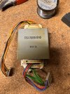
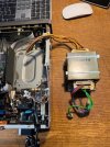
The transformer in situ looks like this: please note next to the primary winding (blue, red brown) the 2 green wires which form one of the secondary wirings 1,9 VAC for the VFD.

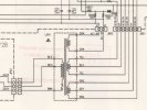
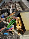
IMG_0001.jpegSchematic.jpegIMG_0003.jpeg

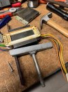
Transformer removed:
IMG_0006.jpeg

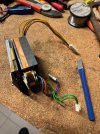
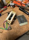
The transformer shielding is metal foil wrapped around and secured with 2 spot welds that I drilled loose.
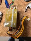
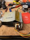
IMG_0009.jpeg


IMG_0010.jpegIMG_0012.jpeg

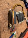
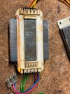
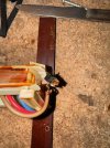
With the shielding removed, I can remove the copper band, but I noticed that the core is welded together.

IMG_0013.jpeg


My question is now: How do I proceed?
Will I be able to replace the fuse if I open the transformer at the side of the primary winding (removing copper belt), or will the green secondary wiring block the access to the fuse?
Do I need to cut the 3 mm welding of the core in order to access the fuse?

I could go ahead without advise, but all experience and know how of this community is welcome before I start cutting up/killing this transformer.

Thank you!
Chris
 
Register to hide this ad
Never understood welding a laminated core like that. That pretty much eliminates the eddy current reduction brought about by the laminated core. As far as repairing the xfmr goes, I don't see how you can get at any internal fuse, since that core is never coming apart absent the use of a saw.
 
Apparently this kind of welding is a common practice, f.e. for microwave ovens. It keeps noise and hum at a low level and is less expensive than using screws. The extra eddycurrent losses make the transformer less efficient.

So I'll go ahead and dismantle the transformer until I can access the fuse.
Anyway, what's there to lose?
 
Years ago I tried to replace the internal fuse in a transformer from a Sansui power amp. It was buried so deep I gave up. From what I was able to find out, this was a common problem with this line of amps. I chocked it up to built in obsolescence. Hopefully yours is easy to get to if your willing to cut through the weld. If you have all the specs for it, you could probably just have a new one made.
 
I would start by removing this plastic piece, and see if you have access to the connections on the thermal fuse.

IMG_00061.jpeg
 
I continued opening the transformer. I used a hacksaw on the welds.
The weld is quite soft and it doesn't take a lot of time to get through them.
A little bump with a chisel separates the I and E.

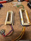
IMG_0019.jpegIMG_0022.jpeg

The windings can be tapped out carefully

IMG_0023.jpegIMG_0025.jpeg

The primary and secondary windings can be separated, also with a slight tap.
Don't mind the mess on workbench ;-)
IMG_0026.jpegIMG_0027.jpeg
IMG_0028.jpeg

I can now easily access the thermal fuse.
@ecluser : you were spot on about the location of the fuse.
However it would not have been an easy job to solder in a new fuse without separating the primary and secondary windings...
It's a 2,5A 150°C fuse.

IMG_0029.jpegIMG_0031.jpeg


As I don't have a fuse at hand right now, I shorted the fuse and temporary rebuilt the transformer to test my receiver.
I kind of 'glued' the I and E with some solder and strapped the shielding around.
When I'm happy with the transformer and the receiver, I need to put the correct fuse and properly weld the I and E together.

IMG_0032.jpeg

Testing:
I no longer measure an open circuit on the primary winding. All secondary measure OK as well.
I installed the transformer and fired up the receiver, using a 40W LBT.

Result: hum, more than expected and full bright light bulb.
I disconnected the secondary windings towards the power supply, but the result is still a full bright LBT.
So there is another problem in the transformer, which most probably caused the thermal fuse to blow.
As there seems to be a short circuit somewhere, I didn't try to measure the secondary voltages on LBT or 230Vac.
So up till now, it was just some time that I spent, but I'm not sure it will be worth the effort and cost to restore this receiver.

How do I proceed? I can easily dismantle the transformer again.
How can I identify which of the wirings is faulty or shorted somewhere?
If I need to rewind, I'll probably need to dip the transformer...
All ideas are welcome!
 
Find a new transformer
That would indeed be the most pragmatic solution :)
However, I'm approaching this transformer problem also as an opportunity to learn.
So I would like to dig a little bit deeper.

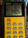
Can I use a DE-5000 LCR meter to diagnose a bit more accurate?

These are the readings on the primary winding (for 230Vac):

This is DC resistance: 13,5 ohm
Compared to another transformer from a 2 x 50W amp this a bit lower: 13,5R vs 17,5R

IMG_0035.jpeg

Ls is 740mH Q 8,2 vs 3,4H Q2,6 on other XF

IMG_0036.jpeg

Rs: the lowest f I can select is 100Hz, while the grid is 50Hz.
Rs at 100Hz: 56R vs 820R other xf

IMG_0034.jpeg

So I notice a significant difference between both transformers where the Marantz xf has clearly much lower values, especially when tested on 100Hz.
I'm a bit rusty on my theoretics here, so please let me know if I'm on the right path with the LCR meter or if I'm straying too much!
I'm also interested in your insights about such values for the secondary windings: 1.9 vac, 2x16vac, 2x32vac.

I'm considering rewinding the primary, just to get to the bottom of it. I only need to measure the wire and find/order it.
I still don't know whether the receiver is worth it...

A big thank you for all your support so far :thumbsup:
 
Apparently this kind of welding is a common practice, f.e. for microwave ovens. It keeps noise and hum at a low level and is less expensive than using screws. The extra eddycurrent losses make the transformer less efficient.

So I'll go ahead and dismantle the transformer until I can access the fuse.
Anyway, what's there to lose?
True. It's broke and you can't make it any broker. There's nothing to lose.
 
You can send that winding off to be rewound if you wished also. But then you do need to ask the question it is worth the effort. That slim line receiver with remote sold for around $500 new.
 
It could be one of the secondary winding that is shorted. Mount only the primary winding on the DBT and see if you have a short.
 
Mount only the primary winding on the DBT and see if you have a short.
That is indeed the test that moves the transformer troubleshooting forward :thumbsup:
Still bright light with the DBT, so I'll focus the next steps on the primary winding.
However there is no visible damage.

Working transformer windings is all new terrain for me, as was the disassembly.

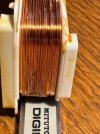
The primary winding is 0.51 mm wire -> 24 AWG 40 mm x 100 mm
A quick estimate of the nr of turns by counting the passes I can see on the surface: about 15 layers, 28 wide = 420 -> Does that make sense for a 2x45W RMS 8 Ohm receiver?
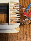
The transformer is capable to take 230V and 240V, currently wired for 230V.
As the windings look crammed in that holder and still need to fit that in the secondary winding (see pictures above), I may have an opportunity to make winding easier by not wiring the extra for 240V.
That would roughly save me one layer. Would that be good practice?

IMG_0040.jpegIMG_0041.jpeg

Next steps:

Order 100 m 24 AWG enamel wire and all other supplies needed for a decent wiring job.
Unwind and count nr of turns.
Find an effective way to rewire: make a jig or something else?
 
It makes sense to rewind only the 230v section of the primary winding, for your application.

It's not clear to me if the primary winding was mounted on the iron core for testing. It should.

If you have a variac, you should also test the secondary winding, mounted on the iron core, on the DBT. Use the 65VAC winding. If there is a short in any of the secondary windings, your DBT will show it. It would be a waste of time to rewind the primary winding if you also have a short on the secondary side.
 
If you have a variac, you should also test the secondary winding, mounted on the iron core, on the DBT. Use the 65VAC winding. If there is a short in any of the secondary windings, your DBT will show it.
OK, excellent idea!
I used my variac, placed in the circuit after the DBT, to test this scenario and use the 65V wiring as primary' fed with 65V.
This yields the same result on the DBT: bright light and a drop to about 20V measured at the primary'.
However I decided to measure the voltage of the other windings and the ratio between the that 65V primary' and the 33V secondary is somewhat OK.
Also the same noise from the transformer was present as in the test with the real primary.

I decided to test what I should have tested earlier on:
Assemble the transformer with primary and secondary wirings (not welded yet, but stuck together), plug it in the DBT without Variac and measure the voltages:

Results:

230V Primary showed 72,5V (after the DBT with bright light) ratio 230V/72,5V = 3,17
65V Secondary showed 20,7V ratio = 3,14
33V Secondary showed 11,7 ratio = 2,82
1,9V Secondary showed 1,1V ratio = 1,73

So, what to conclude here?

Facts:
  1. The thermal fuse was blown, I had to cut open the welds on the core in order to diagnose this correctly.
  2. I shorted the thermal fuse and tested the assembled transformer: DBT bright light & transformer hum
  3. I mounted only the primary winding in the core and tested on 230V: DBT bright light & transformer hum
  4. I mounted only the secondary windings and tested on 65V : DBT bright light & transformer hum
  5. I repeated step 2. from this list and record voltages: something is off with the voltage ratios for the different secondary wirings compared to the theoretical value 3,17
My questions:
  1. Why do I see these different ratios for the different secondary wirings? I have no way to know what these ratio's are for a good SR1200 transformer.
  2. Why do I have a bright light DBT on each test I did? Does it have something tot do with the core not being welded properly? some info on welded cores: https://www.practicalmachinist.com/forum/threads/welding-in-transformer-core.253426/
  3. Did I do something wrong? Is there a better approach?
What are my options?
  1. Find a replacement SR1200 transformer: none for sale where I can see
  2. Find a similar transformer for these voltages and footprint
  3. Manual count of all winding turns in order to answer question 1
  4. Ignore all questions and just weld the core together and test the receiver on 230V
  5. Call it a day and be happy with what I've learned, use the chassis as a donor
Here's what I think:
  • A transformer with a welded core is not efficient (more losses, so more heat in the unit) and not easy to repair.
  • I would expect better from a company like Marantz for a 500$ receiver sold in the mid 90's
  • If it is a piece of Audio gear, or any gear for that matter, that you really want repaired and has a welded transformer, find a decent non-welded alternative
  • Avoid gear with such transformers, but how do you know? Is there a way to identify this via the parts list or schematics in the SM?
  • I'm not inclined to still use a receiver with a welded transformer, seen the downsides of such transformer, so I won't repair this unit.
  • My unit becomes a donor. There's surely some stuff in there that can be recycled.
Any thoughts you have?

I want to thank everybody to think alongside with me and for the support you gave.
 
I think that the fact that the core is not welded might cause hum from the transformer, and lower voltages than expected. With the windings mounted on the E, that part of the core is in some way an electromagnet that attracs the I part. But the attraction force is modulated by the AC sinewave. At the point where you are, I would try to weld the core. With a thermal fuse preferably.
 
At the point where you are, I would try to weld the core. With a thermal fuse preferably.
It's not too much work to continue now I guess.
Thermal fuses are already ordered.
I'm wondering how critical the alignment of the I and E laminations is after the welding? Could misalignment of the E and I cause the strange voltage ratio's?

One time consuming option I still see, is to separate all the laminations and build the transformer alternating the I's and E's as it would have been held together in the traditional way with screws.
I would need to drill the necessary holes in the laminations, but how to get everything perfectly aligned?
Would it even be a viable solution seen the laminations are 'damaged' by the welding?
 
Before you weld it together I would try it with an amp meter in series and no DBT, but otherwise fully assembled.
It will either work or draw so much current you will be reaching for the off switch in a hurry. Either way you will be further along than you are now.
 
Maybe clamp the two halves together and test? As long as there is contact between the two halves of the core, that may work.
 
Maybe clamp the two halves together and test?
I've always clamped the two halves together, trying to align them as good as possible.
The only action left is to actually weld the transformer together. I'm still waiting for the thermal fuses.
 
Before you weld it together I would try it with an amp meter in series and no DBT, but otherwise fully assembled.
I will eventually do that once I have the thermal fuse in and welded everything down.
It's all or nothing from that point on I guess.
 
Back
Top Bottom