• The move to the new server is done. There are some software and database maintenance updates in process. This has us passing the hat around to help out. We appreciate any donations. Seriously, even a dollar helps. The payment page may be found here - https://www.audiokarma.org/support.html

Marantz SR5003 advice on further diagnosing protect mode blinking red light

guy232

Member
Bought used at thrift store, wired it up to speakers and powered subwoofer, turned it on and it played music for a few minutes and then stopped.

With the unit completely disconnected except for the AC cord: as soon as it's plugged into the wall the red power light rapidly blinks until continuously. Pressing POWER does not effect the blinking.

Researched a bit and did the following:
- Left it unplugged for a long time, re-plugged in, same problem as above
- Held down Surround + Exit + Clear for 3-5sec, the unit audibly clicks off for a second but then returns to blinking
- I opened the unit, no obvious signs of damage, clean, fuse is good.

I am reading/researching online but I thought that it may be helpful to see if someone has had any experience with this issue. It appears that it may be a hardware issue based on what I read.

In the meantime I'll update as I make any findings. Thanks for your time fellas!
 
Last edited:
Register to hide this ad
It is most likely going into protection due to a failure in the Power Supply - Chris
Thanks for the lead! So far I have only found old postings online where people have just vaguely said that it was a hardware level issue. Power supply helps narrow it down, I will start searching around for how to go about diagnosing PS related issues & will report back with any findings.

Just figured I'd also link to the sr5003 service manual incase anyone stumbles upon this thread during future searches and is interested in it:
https://www.vintageshifi.com/repert...ge.php?pdf=Marantz-SR-5003-Service-Manual.pdf
 
Looks like one I found dead at a recycler and with a bunch of youngsters picked up as a project.

Shorted output transistor had it in protection and ended up stealing parts from 6th channel to fix the 5 while i awaited enough other parts to order the correct output from BDent. Since my son only has 5 speakers it is still working for him with the replacement part taped on the back. Has been working for him now for maybe 4 years......

It is easy to get hung up on all the computer related dodads and forget the fundamentals like shorted outputs.
 
TL;DR: Checking around power area, noticed 2 connectors had pins soldered bridged together. Double checking to see if this is the way it's supposed to be.
Hosted pics: https://imgur.com/a/BhewAS2

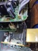
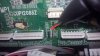
This amp is a bit more complex than I am used to so I may be wrong; I started at the boards which I believe are part of the power supply (Transfer PWB 1 & 2). I first visually inspected it and noticed on each board there are two connectors that have pins that are solder bridged together. I wasn't sure if this was intentional or not so I thought I would ask before I continue.
 

Attachments

  • a1.jpg
    a1.jpg
    81.5 KB · Views: 30
  • 3.jpg
    3.jpg
    100.7 KB · Views: 34
  • 1.jpg
    1.jpg
    82 KB · Views: 30
  • 2.jpg
    2.jpg
    53 KB · Views: 32
Greetings:.
What does the connector go to? Identify the black and 2 white wires origin. Built a DBT for usual power supply suspected.
 
@Binkman

Hail, I didn't have a DBT so I went out today and built one as per your suggestion.

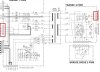
The black and 2 white wire connector (CN93) leads to the MAIN PWB to BN93. Would this specific area (near BN93) be considered the power supply? Or are the two TRANSF PWBs near the transformer considered the power supply?

I am attaching a couple of pictures for reference to help convey my message.

Thank you everyone
 

Attachments

  • connection93.jpg
    connection93.jpg
    80.9 KB · Views: 23
  • diagBN93.jpg
    diagBN93.jpg
    54.6 KB · Views: 21
PWBs near the transformer considered the power supply?
Yes. A ps is basically from ac in to transformer, associated mains caps, rectifier stage(s) connected out to i.e. rails and may be further voltage regulated etc. to other pcb's etc.
 
I understand, thank you.

Are the solder bridges that I shown a design feature or is this a defect caused by solder wave?

I cant find any info online about solder bridge being a good thing/design feature but I thought it may be best to ask before I remove the bridges.
 
More like a factory flub.. somebody probably forgot a jumper trace so they solder bridged it. All adjacent soldering looks good. There's no wave soldering in that unit I see, it's all hand done.
 
Ah, I imagine the bridges aren't the cause of this issue then.

I feel a bit clueless on how to proceed and havent had much luck finding resources that delve into an issue like I'm having on a unit similar enough so that I could learn from. Usually i'm good at googling info to learn how to complete tasks but haven't had much luck in this case.

Or is this type of operation and others like it going to require learning from the ground up via a text book or two? Willing to do that if so.

In regards to hand solder, I assumed that a newer unit such as this would've used an automated process. After searching & learning about reflow, wave and manual processes I agree that this does look manual.
 
Last edited:
Extremely difficult system to learn on. These type units operate on the cpu self test modes. Have you tried the service mode pdf pg 11-13?
 
Looked into the test modes in manual more deeply for a couple hours. As a newbie the wording is very short but it appears that the unit goes into standby like in my situation and I can check a few different pins on IC11 cpu to see if they are outputing "L" or "H" which will tell me what type of error is keeping me in standby, right?

I am researching more to figure out how to test the pin to see if it outputs "L" or "H", does this require an oscilloscope? If so I will get one.

Will update this post in the event that I figure out more in regards to accessing the self test mode values.
 
@redk9258 Aye, after reading the datasheet on the microcontroller (I believe that is what IC11 is called) it seems that H & L are what you mentioned.

My delay has due to me spending time reading, googling & looking through youtube to learn the fundamental skills and related info needed since I was initially basically clueless. I believe that I can understand the service manual tests a bit better:

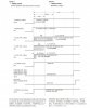
I'm unsure how to understand CHECK 4 which shows a timing chart for normal & abnormal operation. Does the chart show from the moment of plugging the unit into the wall, first it does a _Standby, next it goes through each of the 5 protection checks (pDown, pLineFail, pAmpFail, pCurFail, 5vDown)? The abnormal operation timing chart shows the estimated time it may take for the system to make it way through each of the 5 checks, to help the technician more easily figure out what is failing? And/or help you compare your 20VDC meter reading as the voltage fluctuates over time as displayed in the chart?

Check 2 & 3 involves voltmeter to 20VDC, then (information has been conflicting about where to ground) but either attach black lead to a screw/unpainted chasis OR a copper ground plane/ground pin on pwb. Then connect red to the various points listed, plug the device in and record the reading.

Will report back soon with the results for CHECK 2 & 3.
 

Attachments

  • CHECK_2.png
    CHECK_2.png
    277.3 KB · Views: 16
  • CHECK_3.jpg
    CHECK_3.jpg
    60.6 KB · Views: 12
  • CHECK_4_normal.jpg
    CHECK_4_normal.jpg
    42.9 KB · Views: 12
  • CHECK_4_abnormal.jpg
    CHECK_4_abnormal.jpg
    53.9 KB · Views: 11
When you first plugged in unit.. it was completely dead.. all caps were discharged.. few mins.. into protect mode.
Okay... this unit doesn't justify an O'scope expense.
I assume you performed the factory reset.. clearing out all previous owners settings. disconnect all speakers?

-Dmm voltage checks. neg probe to anywhere on the chassis metal frame. Pos probe to test point.

-diode checks.. set dmm to continuity or ohms. diodes are forward (one way) voltage and you check those power unplugged. touch probes on each side of the diode one way reads 0 or no change. swap leads the the shows a meter or beeps on continuity= good.

On the main A and B boards pg.60 you'll see a number of diodes.. check those. (a bad one is enough to trigger the protect circuit.)

Power supply pg 54 You see 5v 12v, 16v and rail v is 34v. to front main pwb. When you get an error sent to the cpu it disconnects the relay & perhaps also shuts off the 34v rails. basically speaking is how that works.

I would check diodes first.. assure all pcb ground screws are snug, too. poor case handling can mess with ground screws and chassis screws.
 
Thank you for the details and clarifications.

Pulled some PWB out of the way to get visual on Input PWB.

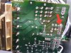
1) One diode (D103) appears to be missing, another factory flub or perhaps part of the problem? [Pic 1]

2) Most diodes checked out only one way with a reading of ~571-610 without beeping

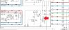
3) D201, D203, D204, D205, D206 beeped when probed both ways with a reading of 0. D202 may have also been this way too. It seems these are all on the same area on the schematic as well. [Pic 2, red error symbol placed next to aforementioned diodes.]
 

Attachments

  • JrHrG6T.jpg
    JrHrG6T.jpg
    47.8 KB · Views: 19
  • diodeLocations1.gif
    diodeLocations1.gif
    39.3 KB · Views: 17

Looks to me as if they weren't sure of their grounding arrangements, so have added back-to-back diodes, capacitor and zero ohm resistor options. If the zero ohm resistor is fitted, that's what you will see.

Note that that entire section is connecting components between the various grounds in the system.
 
SMT's surface mounted components .... I'd be packing it in, today. And I can't help you further as I don't even know where to get the parts or lead free solder advice.. I don't use lead free at all.
imo not worth the headache and time much better stuff to learn on, too.
Good luck mate :D
 
Back
Top Bottom