• The move to the new server is done. There are some software and database maintenance updates in process. This has us passing the hat around to help out. We appreciate any donations. Seriously, even a dollar helps. The payment page may be found here - https://www.audiokarma.org/support.html

Maranz 2500, 2600 Transformer Design

ccheath

Got an Idea!
Subscriber
Maranz 2500, 2600 Transformer Design - Could Use Help.

Since some of us would have such receiver with blown transformer (in my case no transformer), someone would have to at least start on the transformer design.

I have wondered if anyone finally figured out the specifications of this 2500 or 2600 transformer since this old thread: http://www.audiokarma.org/forums/showthread.php?t=91163
 
Last edited:
Register to hide this ad
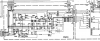
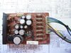
For the last few hours, I have been looking at a couple schematics. One from 2500 and the other from 2600. I also did some verification using my 2500 PS board (P800).

I've been racking my head over this. This does not make sense how the windings have such voltages mixed.

attachment.php


After verifying using my power supply board, everything is starting to make sense.

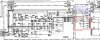
attachment.php


So I rerouted the lines from the transformer symbol. Notice even the GRN and BLU are backward. BLU is for lamps and GRN for filament. [Can anyone verify this?]

attachment.php


I have always thought this route is right but I thought Marantz was able to do something unusual successfully until I found Echowar's thread on Negotiableterm's 2600 restoration. Glenn stated Marantz Service Manual sucks so that means I'll just have to figure that out. Here's what I got so far (NOTE: I'm not able to figure out the 180v yet because it is 180v AFTER the 4.7k 1/2w resistor in the schematic):

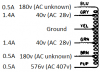
attachment.php


I also found on schematic voltages going to the amplifiers (had to hunt for it and calculate with 1.414):
------ ORG-WHT-ORG & RED-BLK-RED
2500 +/- 87v (62v AC) (124vct)
2600 +/- 94v (67v AC) (134vct)

I am unable to find the voltage for the filament for the CRT tube. Can anyone verify this?

Another little clue is from the Pioneer SX-1980's schematic showing 89v going to the amp with calculation to 63v AC. I also own the SX-1980 transformer (bought just before I even knew I'd get the 2500). I was able to measure the voltage from the output for the amplifiers and came up with 65v (130vct) AC unloaded (input 120v). So I think I'm on the right track so far.

Any further help would be appreciated. Maybe someone has 2500 or 2600 on the bench? Can measure the actual voltage under load (no output with volume to minimum)?

 

Attachments

  • Power supply schematic.png
    Power supply schematic.png
    67.9 KB · Views: 515
  • Power supply schematic - Rerouted.png
    Power supply schematic - Rerouted.png
    76.1 KB · Views: 518
  • Voltage List.png
    Voltage List.png
    7.3 KB · Views: 545
  • 100_1521.jpg
    100_1521.jpg
    115.2 KB · Views: 518
Last edited:
UPDATE: The 180v part I'm trying to figure out is through a 4.7k 1/2w resistor. From figuring out the size of the resistor and ohm, it looks like it can't take any more than 10ma (although the fuse is 500ma). That would mean the voltage drop could be as high as 47v @ 10ma or as small as 4.7v @ 1ma(could be lower). Without knowing how much it draws, I find it could be in range of 130-160v AC.:dunno:

Doesn't look like any way for me to know the voltage for the CRT filament by looking at the schematic either unless it takes the same voltage as the lamps.

Any help?
 
Last edited:
Does anyone know the voltage CRT filament takes? Maybe current too?

And does anyone know the voltage that goes to the 4.7k resistor ending up 180v (see post #3?
 
Is my title wrong, am I in the wrong forum, or is noone interested in helping with the transformer design? :scratch2:
 
There's nothing wrong with your title,it's perfectly clear.

I think there just are not that many 2500/2600's out there.

AK'r lwrs10 recently sold one ,maybe you could pm him to find the new owner and ask if he could measure the winding voltages for you.

Hope this helps,Bob
 
If I had one here, I'd check. But the specs for the CRT might be online if you Google the tube #.
 
There's nothing wrong with your title,it's perfectly clear.

I think there just are not that many 2500/2600's out there.

AK'r lwrs10 recently sold one ,maybe you could pm him to find the new owner and ask if he could measure the winding voltages for you.

Hope this helps,Bob

I apologize for my remark. I kept wondering if I'm in the right spot. :)

If I had one here, I'd check. But the specs for the CRT might be online if you Google the tube #.

That would have been great if you were able to figure the voltage but I understand you don't have it.

For the tube data, I will try again. I found the number somewhere in AK for the tube from the 4400. It doesn't seem to show the number in the Marantz manual. I googled and found no datasheet, yet. If necessary, I may end up having to remove mine to find the number.
 
The CRT for a 2500 is a Hitachi/Toshiba 50TB31 and also fits the 2600/2110/2130.
If you find any specs on this or the 50TB1 that fits the 4400 please share it.

Tom
 
The CRT for a 2500 is a Hitachi/Toshiba 50TB31 and also fits the 2600/2110/2130.
If you find any specs on this or the 50TB1 that fits the 4400 please share it.

Tom

You made it a world easier for me to not have to disassemble yet. Thank you. I will google it and get back here when I find one.

By the way, have you or anyone been able to figure out the 180v part of the power supply?
 
I find something about the replacement "pipe" from the foreign site.

File named like this(note: this is not a link): 4400+tube+rplcmt+eng_V2.pdf

Still looking.
 
Wish I could be of some use.

But looking at your diagrams, that .5A 576V line is the HV supply for your CRT. I'm pretty sure on that.
 
I am guessing the 570V and 180V are for the tube. IMO, you should try to find an off the shelf transformer for +/- 40V supplies, and use a switching supply to develop the 570V and 180V supplies. You can install a small transformer for just the panel lamp supply, or use another switching supply for that. You can feed the switching supplies off one of the 40V transformer taps, or right off the AC line. You will have to design or get someone to design the switching supplies.
 
Wish I could be of some use.

But looking at your diagrams, that .5A 576V line is the HV supply for your CRT. I'm pretty sure on that.

Yes it is. 180v is also the supply for the scope.

The 4400 SM and schematic are here:

http://elektrotanya.com/?q=showresult

I didn't d/l the files to look at them but scan quality is usually very good.

Thank you Sam. It got me closer idea what to expect on the 180v supply. Still need the heater voltage.

I am guessing the 570V and 180V are for the tube. IMO, you should try to find an off the shelf transformer for +/- 40V supplies, and use a switching supply to develop the 570V and 180V supplies. You can install a small transformer for just the panel lamp supply, or use another switching supply for that. You can feed the switching supplies off one of the 40V transformer taps, or right off the AC line. You will have to design or get someone to design the switching supplies.

I thought about this before but I wanted to have one transformer completely custom for this particular receiver. I'm hoping it's possible. But, because you brought it up, I have been brainstorming of what resources I have to even get that receiver to power up. I thought about using my SX-1980 transformer to power those two amps, the 180v supply, and the lamps. The other transformer pairs to power +/- 40v supplies. The only thing I'm lacking is 576v (400v transformer) and the scope CRT heater. I might try using the voltage tripler for the 576v supply. Sounds wild but should work. But, I still don't know the heater voltage.
 
Looking at the 4400 diagram, I was able to find the voltage BEFORE and AFTER the 2.2k resistor. 215v before and 200v after. That's 15v drop across the 2.2k resistor. That should bring it to about 7ma. So for the 180v supply in 2500/2600. If it's 7.5ma it would be 35v drop from 215v. If it's 6ma, it would be 28v drop from 208v. Now it narrows the voltage range to 147-152v AC. STILL need the heater voltage. I don't want to guess the voltage for the CRT and ending up destroying it.

So far I am able to come up with this:

+/- 40v using ~29v ac

180v using 147-152v ac

576v using 407v ac
 
Only thing left is I don't know and can't find the CRT heater voltage requirement. Do anyone know?
 
Back
Top Bottom