You are using an out of date browser. It may not display this or other websites correctly.
You should upgrade or use an alternative browser.
You should upgrade or use an alternative browser.
Maranz 2500, 2600 Transformer Design
- Thread starter ccheath
- Start date

Good luck in getting it sorted out, cc. I will talk with my tech who restored my 2500 and see if he can't help you out.
Thanks. I will get it sorted. BTW, what are you having done to your 2500?
So you got a tranny for it?
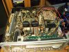
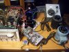
I wish but no I don't have it yet. I'm using an SX-950 transformer running on Variac. SX-1980 transformer direct since it's only a few volts higher than the original. Tomorrow, I'm going to hook up the tube. It's gonna be a little tricky using another secondary from the SX-1980 transformer to power up 180v supply and a tube transformer with variac to power up -576v and a stand alone 6v transformer with variac to power the filament. Total would be 4 transformers and 3 variacs. It'll be on life support.

Any pics of your progress?
I am taking pictures. I'll post them when I get it all together.
Last edited:


It sounds as if it needs a major deoxit bath and a real good overhaul. It's running very good when it runs right but sometimes it gets static otherwise sounds full and powerful. All the dial lights are out. FM and AM works very well. Both channel on preamp and main amp works well. I didn't check the phono preamp since I don't have much concern for it at this time but I would imagine it should work. I checked the BIAS and DC offset. Both are good but bias a little low on both side. I didn't do any adjustment on it in fear of possible damage from possible flaky trimpots. The Scope looks like 1/2 the horizontal is dead and vertical is fine.
The voltages I came up with is as follows:
Lamp = 7v
CRT filament = 7v
-576v supply = 430v
180v supply = 160v
+/-40v supply = 30v (60vct)
Main amp (+/- 87v rails) = 65v (130vct) per channel
I haven't figured the current yet but eventually will get there.
The voltages I came up with is as follows:
Lamp = 7v
CRT filament = 7v
-576v supply = 430v
180v supply = 160v
+/-40v supply = 30v (60vct)
Main amp (+/- 87v rails) = 65v (130vct) per channel
I haven't figured the current yet but eventually will get there.
Attachments


anderslober
Yikes...not again!
That is great! Really excellent work..............now all you need to do is drill some holes and fix all the trannies to the top chassis....it'll be beautiful!

Big Tuna
Too Much Power!
cc, from what I can see with your pic, you don't have the scope pointer centered. Turn the source input to any input without audio playing and center the dot on the screen. :thmbsp:The Scope looks like 1/2 the horizontal is dead and vertical is fine.

That is great! Really excellent work..............now all you need to do is drill some holes and fix all the trannies to the top chassis....it'll be beautiful!
That's a great idea!! :yes: Tell you what. I'll do that and when I'm done, then we'll trade our 2500s. That way you'll have a Marantz full of warts. Deal?
cc, from what I can see with your pic, you don't have the scope pointer centered. Turn the source input to any input without audio playing and center the dot on the screen. :thmbsp:
That is deliberate. I had it adjusted where the dot or "slit" (I think it should be dot) is in the center of the circle. It'll bend the 2nd half that it just cuts straight down. So, I centered it to the 2nd half to get the full phase effect.
That picture with the transformers and variacs is amazing. I can't believe it runs! Great job on figuring it all out.
Will you be able to get a custom built transformer once you have all the voltages and current figured out?
That is what I'm hoping for. I am already loving the sound of that receiver. The current shouldn't be too hard to figure out on the lamps, scope, and tuner/preamp. I think the hard part will be figuring out the main amp current requirement.
Last edited:
anderslober
Yikes...not again!
ccheath.....utterly fantastic..........need your help.......what is YOUR cap value at CCO8 buffer amp board......please check......thanks.
Warted marantz 2500..........................sounds great to me! HIFI history in the making! HIFi-separates in ONE box!
Warted marantz 2500..........................sounds great to me! HIFI history in the making! HIFi-separates in ONE box!
ccheath.....utterly fantastic..........need your help.......what is YOUR cap value at CCO8 buffer amp board......please check......thanks.
Warted marantz 2500..........................sounds great to me! HIFI history in the making! HIFi-separates in ONE box!
Are you referring to PC01 FM buffer amp board? If so CC08 cap value is 10uf 16v.
anderslober
Yikes...not again!
yes, that is the cap.......ok...thanks a'million.......I'll change mine back to a 10uf.....check page 40 of the manual and the scat...it says 4.7uf/35v......thats marantz for ya'!
Marantz 2500
Check out C812, it is a 350v part yet the manual states that there is 576 volts across this capacitor.
I have a blown 2500 xfr and this is the only winding that I am not sure of. Since my 2500 never worked after I bought it I cannot confirm that -576v actually exists across C812.
The way they have drawn the xfr schematic is stupid. The ground wire should be shown as a centre tap on this multi tap winding.
Anybody have further insight into this "-576v vs C812" issue?
Steve Mantz
Check out C812, it is a 350v part yet the manual states that there is 576 volts across this capacitor.
I have a blown 2500 xfr and this is the only winding that I am not sure of. Since my 2500 never worked after I bought it I cannot confirm that -576v actually exists across C812.
The way they have drawn the xfr schematic is stupid. The ground wire should be shown as a centre tap on this multi tap winding.
Anybody have further insight into this "-576v vs C812" issue?
Steve Mantz
IIRC: there's TWO 350v capacitors in series for -576v. I'm going to check and confirm. As for the transformer wiring in the schematic, it's almost all wrong. If you look in post #2, you'll see the correct routing in the red box. Post #48 shows the resulting voltages in my attempt to power my 2500 with a missing transformer.
EDIT: I didn't check in my 2500. But I did check in 2600 model schematic and I looked at the pic of my 2500's board on post #2. It shows TWO 350v caps in series. It looks like C811 and C812 in series.
EDIT: I didn't check in my 2500. But I did check in 2600 model schematic and I looked at the pic of my 2500's board on post #2. It shows TWO 350v caps in series. It looks like C811 and C812 in series.
Last edited:
JuanPabloCue
New Member
It sounds as if it needs a major deoxit bath and a real good overhaul. It's running very good when it runs right but sometimes it gets static otherwise sounds full and powerful. All the dial lights are out. FM and AM works very well. Both channel on preamp and main amp works well. I didn't check the phono preamp since I don't have much concern for it at this time but I would imagine it should work. I checked the BIAS and DC offset. Both are good but bias a little low on both side. I didn't do any adjustment on it in fear of possible damage from possible flaky trimpots. The Scope looks like 1/2 the horizontal is dead and vertical is fine.
The voltages I came up with is as follows:
Lamp = 7v
CRT filament = 7v
-576v supply = 430v
180v supply = 160v
+/-40v supply = 30v (60vct)
Main amp (+/- 87v rails) = 65v (130vct) per channel
I haven't figured the current yet but eventually will get there.
nice thread_:
http://www.audiokarma.org/forums/showpost.php?p=4692321&postcount=2
But... in the J802 Yellow is the only common color.
The P800 i have are AP16S 94V-1
YG2219002-0 from Serial No. U010258
&
YG2219002-2 from Serial No. U070148
Anyway...
I have a working Marantz 2500 dual transformer...
the voltages are different than your measurements...
i dont know how to measure the J802.... gnd to each pin? sides to each pin?
im a bit confosed by the J801 Green & J802 Green purpose in my P800/Transformer.
also the P900-J906 voltages, & the P800-R819 ?
here is what i got so far:
transformer is totally removed from the circuit.
transformer is connected to PS Audio Power Plant Premier, in Non-Multiwave mode... = flawless 120.4v~120.5vac.
MW-mode gives 122vac + 3rd Order Harmonics.
anyway... here are the results:
**********************
120.4v~120.5v AC
*****
PZ01<---P800-J803<--fuses<---P800-J801-->Blue = 9.3vac<---xfrm
**********************
xfrm-->P800-J801-->Green = 7.2vac-->fuses-->P800-J804-->P900-->Scope
**********************
**********************
P800-J801=
1= j803 1&2
2= fuse-->j803 3
3= fuse-->j804-6
4= diodo-q807(-)-->c811(-)-->j804-5
**********************
YG2219002-0 P800-J804= (pcb.schematics)
1.6= +15.00vdc
2.5= -15.05vdc
3.4= +346vdc
4.3= gnd
5.2= -449vdc
6.1= -449vdc
(schematics)
P800-J804-1-->P900-J914-5
P800-J804-2-->P900-J914-4
P800-J804-3-->P900-J914-3
P800-J804-4-->P900-J914-6
P800-J804-5-->P900-J914-1
P800-J804-6-->P900-J914-2
**********************
YG2219002-0 P800-J805=
1=5= +14.00vdc
2= -33.7vdc
3= +33vdc
4= gnd
5=1= +14.00vdc
**********************
**********************
120.4v~120.5v AC
Primary:
RED/Dark & Blue = 186mH - 1.0ohm
167.3mH~168mH~1.5ohm
0.13H~0.14H
182.1mH~3ohm
190mH~2ohm
************************
Amp1
Red-Black-Red
red-red = 1.4ohm - 178mH = 118vac
3ohm~190mH
red1-black = 54.6vac
red2-black = 63.3vac
************************
Amp2
Orange-Black-Orange
Orange-Orange = 145.3mH - 1ohm (-00.2~00.3ohm) = 107vac
3.2ohm-146mH
Orange1-Black = 52.4vac
Orange2-Black = 54.6vac
************************
************************
P800-J802
Purple-Green
blue-purple 15ohm - 0.55H~0.61H
blue-brown 12.25mH - 1.8ohm
blue-gray = 1.8ohm - 13.45mH
blue-yellow = 43.7mH - 3.5ohm
blue-green = 14.8ohm - 0.55H
***
blue-yellow-brown.
blue-brown = 29.1vac
blue-yellow = 58.2vac
brown-yellow = 29.1vac
***
Gray-Yellow-Purple
*Gray-Purple = 335vac
Gray-Yellow = 88.8vac
Purple-Yellow = 246vac
*Yellow-Green = 321vac
************************
************************
P800-J801
green-green = 0.535mH - 00.6ohm = 7.2vac
blue-blue = 00.6ohm - 0.582mH = 9.3vac
************************
Attachments

Last edited: