• The move to the new server is done. There are some software and database maintenance updates in process. This has us passing the hat around to help out. We appreciate any donations. Seriously, even a dollar helps. The payment page may be found here - https://www.audiokarma.org/support.html

MC-2105 Driver board updates - a few specific questions

Refugee

Hurricane Refugee
Subscriber
I have a 2105 that I completely recapped about 2 years ago. I posted about the restoration when I did it:

The amp has been sounding great but lately I hear some snap crackle pop on the left channel that I have not diagnosed yet. I am going to pull the amp and try some cleaning and switching of the boards to find the problem but while it is out of the system I want to do a few things that I did not do during the recap.

I want to go ahead and finish the job by updating the output driver boards according to the service bulletin/kit instructions that I have found posts about on AK. There are some suggestions that I don't quite understand that I would like some clarity about. I will refer to the left channel part numbers in the questions for brevity. Most of these questions are about the transistors since I have limited experience picking new/changing transistors.

1.) It is suggested that all the Bias Resistors on the board be replaced as they are very critical. Which ones would these be?
2.) The instructions indicate the replacement of Q111 and Q113. Should I purchase as matched pairs, either as the npn/pnp pair, or as matched for the left and right boards, or matched both ways?Is it even possible to purchase as matched pairs or do I need to learn to match them myself and buy a certain number of them to go through?
3.) Q107(NPN) and Q109 (PNP) are referred to as a Darlington Pair and/or Sentry Monitors. When purchasing replacements do I need to get matched pairs of these? ( this is not part of the update and will only be done if necessary)
4.) I did purchase the replacement diodes D103 for the thermal tracking from the factory when I did the previous work to the unit. I plan to leave the original diodes installed since they seem to be working fine and keep the new as backup. Is this what you guys would suggest?
5.) Q101 and Q103 - Would you guys suggest replacing?
6.) Q105 - Replace or leave?

7.) I also plan to replace the inductive resistors on the heat sinks and re-seat the output transistors on the heat sinks with new thermal paste. Do you guys think this is prudent? Do I need to get the resistors from the factory or will any wirewound of the same type that are not sold as non-inductive do the job? I think all the OTs are ok but I guess I will try to test them with a multimeter while I have them out.

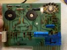
Below is a scan of my board with some notes from two years ago. The resistors are noted in red what they were marked as and smaller in blue what they tested as in circuit. All the 5% resistors are highlighted, the rest were 10% tolerance.
Also there is a pic of the schematic of the board and an attachment of the update instructions from the factory.

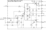
1708965222042.png

1708966021355.png
 

Attachments

Register to hide this ad
So I placed an order with the factory to do the update. I asked about matching of transistors and was told that they are not matched and that they 'have been sending these out without incident for years'. I will have to take their word on that.
The most expensive parts were the heatsinks but I could not find any at the usual outlets that were the same shape as the ones the factory used.

Here are the current part numbers that I ordered for the update.
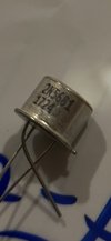
Q111,112 - old part 132-038 | new part 132-153
Q113,114 - old part 132-039 | new part 132-154
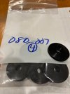
Heat sinks - part# 080-007 (four)
The other parts for the update I ordered from digi/mouser when I recapped the board a few years back. They are:
18ohm 1/2W resistors (two)
680pf COG disk cap (four)
That takes care of the official update.

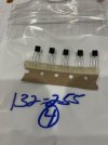
I also ordered replacements for Q101,102,103,104. Original part number 132-515 | new part 132-255. I think these are drop in replacements that will not need any resistors adjusted to match. (I'll let you guys know when I do the job)

For the outputs on the heatsink I went ahead and got the 5W resistors from the factory as I have read that the inductance in these resistors is part of the circuit and don't need to add variables/problems to the job.
.56ohm 5W (four)
.33ohm 5W (ten)

I really still don't feel sure which resistors on the boards are the bias resistors but, since I will check them all anyway, I will procced without knowing.
I did not get the sentry monitor (Q107,108,109,110) transistors. I read that when I test the amp on a scope I can see if the waveforms clip symmetrically and if not then they may be a problem so I will wait and see on those.

The factory said at least two weeks for the parts so an update will take a while.
 
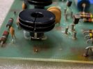
I just finished performing the update using parts from Mouser and Electronics Surplus. Electronics Surplus had the RCA 2N5320, Motorola 2N5322, and cylindrical heat sinks for TO-39 devices.

The stabistors needed to be moved to make contact with the bottom of the new transistors. I had to shorten the insulated sleeving and leads to get the stabistors to sit under the transistor. I applied light pressure to the transistor while soldering so it would make good contact with the stabistor.

I didn’t change any other transistors on the driver board, just the cap and resistor changes per the bulletin.

IMG_8279.jpegIMG_8275.jpeg
 
Last edited:
I wonder about the heatsinks you used and whether they offer enough dissipation as compared to the specified devices.

Also curious as to how much clearance is between the TO5 heatsink and the chassis-mounted heatsinks when the board is installed.
 
I wonder about the heatsinks you used and whether they offer enough dissipation as compared to the specified devices.

Also curious as to how much clearance is between the TO5 heatsink and the chassis-mounted heatsinks when the board is installed.
What specified devices? Of the threads I've found that discuss the bulletin, this type of heatsink seems to be the most common. What is McIntosh providing that is different? The old multi-piece silver one that went under the original transistors is specifically replaced in the SB.

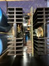
The clearance between these heatsinks and the large output heatsinks is quite large. I can't get a good photo at the moment because the cage is installed, but there's probably 1/4" between the top of these TO-39 heatsinks and the output heatsinks. The standoffs keep the driver board from wiggling.

IMG_8330.jpg
 
Last edited:
I just finished performing the update using parts from Mouser and Electronics Surplus. Electronics Surplus had the RCA 2N5320, Motorola 2N5322, and cylindrical heat sinks for TO-39 devices.

The stabistors needed to be moved to make contact with the bottom of the new transistors. I had to shorten the insulated sleeving and leads to get the stabistors to sit under the transistor. I applied light pressure to the transistor while soldering so it would make good contact with the stabistor.

I didn’t change any other transistors on the driver board, just the cap and resistor changes per the bulletin.

View attachment 3134133View attachment 3134134

Thanks for sharing your experience and the part #s and sourcing. So no matching of the transistors was required? I assume you put the jumpers on the back side as per the Service Bulletin. It looks great. The stabistor placement looks perfect. Is that the original stabistor? I plan to use the original when I do mine but purchased two for backup.

I would suggest replacing the electrolytics on the board also. (C102,103 and C122,123).
 
I wonder about the heatsinks you used and whether they offer enough dissipation as compared to the specified devices.

Also curious as to how much clearance is between the TO5 heatsink and the chassis-mounted heatsinks when the board is installed.
This concern is why I paid too much for the heat sinks from the factory (and just to make the job look more factory).
McIntosh's older stock heat sinks are discontinued as far as my searches indicated. I could not find them anywhere. The major difference is that the fins are a larger diameter, but then again there are only two fins and the smaller diameter sinks that @crv00 used have three fins so maybe that is a wash as far as heat dissipation. IDK.

I have equipment that I take chances with - and then I have this amp. I have had it for 30 years and have built my system around it. I tend to go the safest route I can with the 2105 and overthink everything.
 
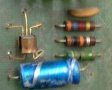
Does anyone know if the differential pair, 'the single package six legged spider' at the top right of the board, (Q101,103) in the picture that @crv00 posted indicates an older version of the board than one with two discrete transistors?
My boards have discrete transistors in that location (Q101,103) and UFO looking sentry monitors (Q107,109)

I can't help but think that the single package would track better because of thermal coupling, but maybe the mirror like circuit makes perfect matching and tracking a moot point.
 
Does anyone know if the differential pair, 'the single package six legged spider' at the top right of the board, (Q101,103) in the picture that @crv00 posted indicates an older version of the board than one with two discrete transistors?
My boards have discrete transistors in that location (Q101,103) and UFO looking sentry monitors (Q107,109)

I can't help but think that the single package would track better because of thermal coupling, but maybe the mirror like circuit makes perfect matching and tracking a moot point.
I’ll double check but I think the six legged device on my board is actually two three legged devices (TO-92?) clamped together by a metal band. Hopefully I’ve got a photo to confirm since it’s all assembled again.

Edit: @clinic-audio’s post from 9 years ago suggests it’s two TO-92 devices clamped together:
https://audiokarma.org/forums/index.php?threads/parts-help-mc-2105-transistor.647848/#post-8619544
 
Last edited:
I’ll double check but I think the six legged device on my board is actually two three legged devices (TO-92?) clamped together by a metal band. Hopefully I’ve got a photo to confirm since it’s all assembled again.

Edit: @clinic-audio’s post from 9 years ago suggests it’s two TO-92 devices clamped together:
https://audiokarma.org/forums/index.php?threads/parts-help-mc-2105-transistor.647848/#post-8619544
It does look that way. I was thinking a small piece of copper tubing might be used to couple the two transistors with a little heatsink in between. I ordered these transistors from the factory and may change them if I find they are the cause of the noise (snap crackle) on the left channel. If so I will try to couple them this way. If they are not causing problems I may try to couple the ones that are already there.
 
It is two TO-92 devices clamped together, and without parts that have the exact same pin configuration it is extremely difficult to get everything lined up and back together.

I ditched the clamp and used the original layout when I repaired my 2105 when those transistors had failed a while back. It worked, but probably wasn't ideal. Surprising so many different revisions of parts using the same circuit board.
 
Usually when transistors are clamped together, it is because thermal coupling is very important. I would duplicate if in any way possible.
 
If they don’t get too hot for plastic then I’d use mini zip ties. That was the solution for some diyaudio project I did (Pass F5?).
 
I ordered four of the part number for these transistors from the factory. ( two for each board)
Now I am wondering if I will get four coupled pairs 1709564978612.png or four discreet transistors1709564880201.png. I will let you guys know when they arrive.
 
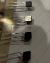
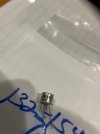
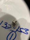
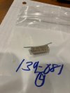
I finally received my parts from McIntosh. In case anybody is interested...here are the parts they sent. The differential pair was sent as discreet transistors - not coupled pairs. They sent 5 of these and 5 heatsinks though I ordered 4 and was only charged for four - always better to have too many than not enough so - great.
It will be a few weeks before I start on the boards so I will post then.
Thanks for the comments above and hopefully having pics of the parts will help the next guy when ordering parts.
 

Attachments

  • heat sink.jpg
    heat sink.jpg
    53.9 KB · Views: 50
  • 132-255close.jpg
    132-255close.jpg
    60.3 KB · Views: 49
  • 132-255.jpg
    132-255.jpg
    53 KB · Views: 50
  • 132-154close.jpg
    132-154close.jpg
    39.7 KB · Views: 48
  • 132-154.jpg
    132-154.jpg
    33.5 KB · Views: 45
  • 132-153.jpg
    132-153.jpg
    37 KB · Views: 46
  • 33 ohm.jpg
    33 ohm.jpg
    57.8 KB · Views: 44
  • .56 ohm.jpg
    .56 ohm.jpg
    46 KB · Views: 47
I’m guessing you will try to reuse the metal clamp to hold the differential pair together. Or did they send something for that?
 
They did not send anything. I don't think mine had a clamp - can't remember. If it is there I might try to use it. I have some soft copper tubing that I may try to fashion something out of - not sure yet. I have seen many pics online that do not have them coupled so I know it would work that way, but I will couple them somehow. I have to figure out if the legs are configured the same way as the original.
 
They did not send anything. I don't think mine had a clamp - can't remember. If it is there I might try to use it. I have some soft copper tubing that I may try to fashion something out of - not sure yet. I have seen many pics online that do not have them coupled so I know it would work that way, but I will couple them somehow. I have to figure out if the legs are configured the same way as the original.
Ah, gotcha. I thought this photo from your earlier post was a close up of your actual driver board:

1711647651726.png
 
Back
Top Bottom