
• The move to the new server is done. There are some software and database maintenance updates in process. This has us passing the hat around to help out. We appreciate any donations. Seriously, even a dollar helps. The payment page may be found here - https://www.audiokarma.org/support.html

MC-2105 Driver board updates - a few specific questions

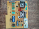
I attached a copy of my 043899 board for you to look at. You can see that the 028 transistor has a date code of 912 and the 038 and 039 transistors are original with the diode under the left. I am thinking that in the late 80's I may have replaced the carbon resistors because I have a box of them I kept over the years that look like the parts from the two boards. I have no issues with the boards, in fact the amplifier works well and sounds good. I say good because it is not as good as the Marantz 16B I went through driving my Martin Logans. This is what got me started on this MC2105.

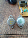
What is funny about this amplifier is half of the output has the older 132-042 yellow transistors and the other side the newer 132-070. The date codes on the 132-043's are 1969 also as is the TO-66 on the pc board.

Now the fun part with this amplifier and where I am headed. I have gone through a number of the TO-3 transistors of both varieties and observed their operating characteristics on my curve tracer. I drew the same conclusion that got me started on the Marantz amplifiers doing some well deserve updating on them. You could almost hear these transistors on the curve tracer, just kidding, but having removed a number of SJ Motorola from the Marantz amplifiers and examining them with the curve tracer I drew the conclusion that most semiconductors from 50 years ago are fair at best.

The yellow 132-043 Mc transistors have low gain, you would hope for more, but they are linear in operation. The green 132-070 Mc transistors have much more gain but they are not flat, rather crappy observing the steps.

Are you still with me? I believe way too much emphasis is placed on the fT of the transistor and whether it should be used as a driver or a final in an emitter follower configuration. The talk about possible oscillation or not sounding like the "factory original" because of not having a high enough fT transistor as a driver to me is way over exaggerated. Yes, some amplifiers will have issues when replacing transistors. fT and gain are important. So is local and overall feedback in the design.

I need to go to Kroger. I am making tuna salad for Good Friday. I keep it short because I will be going back and look at those two boards and decide what I will do with them after looking at the powered up on the bench. If you get to those outputs and decide to use the MJ15003, it is a good choice. Dead transistors (low gain) put a little more strain on the drivers and their operating point. I need to look at the three available choices I have for drivers: MJ15018, MJ15024 and MJ21194. Some people perhaps will comment that the MJ21194 is a final transistor. From what I observe, it is far better than any of the two choices the factory supplied in these amplifiers with good gain (equal to the 132-070), low saturation Voltage and very, very linear.
 

Attachments

  • 1711722996468.png
    1711722996468.png
    891.7 KB · Views: 51
  • 1711723961353.png
    1711723961353.png
    934.4 KB · Views: 52
Before I leave, I was laughing to myself that I could see me rolling driver transistors like tubes in this amplifier. Funny, but true. As long as those finals are good, they would have the least impact on the sound. Yes, the Marantz Model 16B is that good and I chose the MJ15003/4 combination. Just listen to a high-resolution file of America's first album and the first three songs will give you all you need to know about the equipment you are listening or using...
 
Did you replace the old electrolytics? That is a must.
I have a good capacitor checker I use to evaluate the part looking for not only value but ESR, tangent, etc. I do not just assume they are all bad. What I will do is evaluate if the circuit could use a non-polar capacitor in place of an electrolytic if it is in the signal path. There are quality parts from the later 60's and early 70's that withstood the test of time. I will continue to use them. I get a real kick out of seeing some people replace supply side capacitors with "boutique" parts that have nothing to do with the sound. Whatever make you feel good these days...
 
I agree with not replacing electrolytic caps with boutique ones that cost $$$-- but in power supplies and amplifiers leaving old ones in is a ticking time bomb. Maybe they slowly lose value and open, maybe they short and take out lots of other components.

I also spend a bit more for a name-brand part from a reputable distributor like Mouser, Digi-Key, or Newark--hopefully no counterfeit ones from them.

I recapped all of my equipment from the 80s and older -- left all the 90s+, although it's getting old now too.
 
I attached a copy of my 043899 board for you to look at. You can see that the 028 transistor has a date code of 912 and the 038 and 039 transistors are original with the diode under the left. I am thinking that in the late 80's I may have replaced the carbon resistors because I have a box of them I kept over the years that look like the parts from the two boards. I have no issues with the boards, in fact the amplifier works well and sounds good. I say good because it is not as good as the Marantz 16B I went through driving my Martin Logans. This is what got me started on this MC2105.

What is funny about this amplifier is half of the output has the older 132-042 yellow transistors and the other side the newer 132-070. The date codes on the 132-043's are 1969 also as is the TO-66 on the pc board.

Now the fun part with this amplifier and where I am headed. I have gone through a number of the TO-3 transistors of both varieties and observed their operating characteristics on my curve tracer. I drew the same conclusion that got me started on the Marantz amplifiers doing some well deserve updating on them. You could almost hear these transistors on the curve tracer, just kidding, but having removed a number of SJ Motorola from the Marantz amplifiers and examining them with the curve tracer I drew the conclusion that most semiconductors from 50 years ago are fair at best.

The yellow 132-043 Mc transistors have low gain, you would hope for more, but they are linear in operation. The green 132-070 Mc transistors have much more gain but they are not flat, rather crappy observing the steps.

Are you still with me? I believe way too much emphasis is placed on the fT of the transistor and whether it should be used as a driver or a final in an emitter follower configuration. The talk about possible oscillation or not sounding like the "factory original" because of not having a high enough fT transistor as a driver to me is way over exaggerated. Yes, some amplifiers will have issues when replacing transistors. fT and gain are important. So is local and overall feedback in the design.

I need to go to Kroger. I am making tuna salad for Good Friday. I keep it short because I will be going back and look at those two boards and decide what I will do with them after looking at the powered up on the bench. If you get to those outputs and decide to use the MJ15003, it is a good choice. Dead transistors (low gain) put a little more strain on the drivers and their operating point. I need to look at the three available choices I have for drivers: MJ15018, MJ15024 and MJ21194. Some people perhaps will comment that the MJ21194 is a final transistor. From what I observe, it is far better than any of the two choices the factory supplied in these amplifiers with good gain (equal to the 132-070), low saturation Voltage and very, very linear.
Thanks for the pics. It seems that every pic I see of those output boards is different - LOL - so many versions and years in production.

Oh! to have a real curve tracer..... That would be nice. It is good to see your findings.
 
I also spend a bit more for a name-brand part from a reputable distributor like Mouser, Digi-Key, or Newark--hopefully no counterfeit ones from them.
These guys have the best search engines. The user interface at these major sites (with their search capability, list making functions, comment fields) is powerful and well worth the slight markup.
 
I am really enjoying this post and the company I am keeping here. Last night I finished updating the drivers and finals in The MC2105 I have. I used NOS MJ21018 MOSPEC NPN drivers that all were matched using the curve tracer. The outputs were ON Semi MJ15003G TO-3 transistors, also matched with DC gain at lower currents around 60 to 70 if I recall correctly. The MOSPEC drivers were killer on linearity and slightly higher on gain than the outputs. I ended up listening to it and I won't get into the detains now, but I am really happy. I measured one channel with 20mV positive and the other 40mV negative at the brown wires (output) for the DC balance. Trying to measure the bias current across the 0.33 Ohm resistors, I really saw squat (really little). I will look at that later.

I did not perform any changes to the pc board or pre-drivers for two reasons. First, I wanted to know how the amplifier would react to the changes of all the TO-3 transistor components which it did favorably without seeing Voltages out of the norm. Sounds Great! Bias, DC offset, I'll get to that later (if at all). Secondly, having repaired these amplifiers in my college days for the local Mc dealer on Chicago's Southside, we never did the 044-980 update on every MC2100 or MC2105 amplifier that came through the door. The MC2300 amplifiers were a different story.

As far as the MC2100 and 2105's, everyone did not listen to AR3A's at 1/3 power level for an extended period of time. Also, everyone did not have their amplifier in an equipment cabinet in a bookcase with no air circulation. I have helped others over the years with their Mc products like the ones we are discussing with MC Clinic stickers on the heatsinks around the period of the service bulletin. It just was not required or warranted on everyone's amplifier. Those out here leaving the impression that rubbing shoulders with Dave O'Brien make them the final word are a little windy or long in tooth. The original RCA pre-drivers are perfectly acceptable under most circumstances. Those with these home amplifiers did not need 10 Watt transistors or a drop in final output bias current to make them work satisfactory.

I would be curious after a brief warmup, what Voltages you are seeing at the output for dc balance and if you would carefully measure across the current sharing resistors (balancing) the 0.33 Ohm. Some if not most of the readings can be done at the pc board connector on the bottom of the amplifier.
 
These guys have the best search engines. The user interface at these major sites (with their search capability, list making functions, comment fields) is powerful and well worth the slight markup.
Yes, it appears to work well without having to open a lot of screens on your computer.
 
After I clean up the work area, I will use the audio oscillator and HP distortion analyzer to measure the distortion and look for crossover notch with the scope. I will let you know the findings.
 
After I clean up the work area, I will use the audio oscillator and HP distortion analyzer to measure the distortion and look for crossover notch with the scope. I will let you know the findings.
I can't wait to see the results. I will post my findings when I get this amp on the bench. I'm hoping to get to it around the end of april.

As far as dc offset goes I always thought that was a non issue because of the autoformers.
Question - the NOS MJ21018 MOSPEC NPN you put in all the positions that are not isolated from the heatsink and the ON Semi MJ15003G go in place of the isolated ones on the heatsink?
 
I can't wait to see the results. I will post my findings when I get this amp on the bench. I'm hoping to get to it around the end of april.

As far as dc offset goes I always thought that was a non issue because of the autoformers.
Question - the NOS MJ21018 MOSPEC NPN you put in all the positions that are not isolated from the heatsink and the ON Semi MJ15003G go in place of the isolated ones on the heatsink?
Yes, it would be good that all goes well for you. Keeping my fingers crossed.

The dc offset is somewhat important to know that the amplifier is performing well and is balanced. The values for direct coupled amps without autoformers are in the order of less than +/- 50mV like the Marantz units I enjoy so that is what I shoot for. Bias and DC balance were a fixed thing on these amps but the MC2505 that came just just before the 2105 and 2100 had both adjustable in the early version. DC balance was done on the input board, but a coupling capacitor between sections and a slight variation of the input board prevent one from copying it directly for the 2100/2105. If you need to know or run into an issue later I can show you what to do with the properties around Q105 and Q106 on the MC2105. Bias also can be moved slightly with a resistor change.

The bottom drivers where I used the MJ15018 and the middle outputs where the MJ15003's are do not have the pads. The top output MJ15003 transistor where the heatsink has the four sandbar or wire wound resistors uses the pad for isolation for the sentry circuit to perform. The other top output has none. I am listening to Groove Holmes on the system now with the 2105 in place and it's not even buttoned up!
 
After I clean up the work area, I will use the audio oscillator and HP distortion analyzer to measure the distortion and look for crossover notch with the scope. I will let you know the findings.
Well. How did your measurements go?
I’m getting ready to go through a mc2105 & reading up on how folks have faired …thanks mucho
 
Well. How did your measurements go?
I’m getting ready to go through a mc2105 & reading up on how folks have faired …thanks mucho
When I was finished with the amplifier, I recall making a few measurements of some of the direct current Voltages and was satisfied with the readings. I was listening to it for a few days and along with the Voltage measurements I was using a thermal gun to observe the temperatures of the transistors and heatsinks. I concluded all was good and finished putting the screws into it. I didn't do more because most of my time was spent working on a 1964 Studebaker Daytona that went on the Hot Rod Power Tour last year and will again this year. If your need any help I will be looking at the postings now and then but I have my patience being challenged trying to remove bearing savers from the axle tubes of a 1984 302 Mustang so I can install new axles.
 
Thanks for the response…..Cool car work man. Ya bearing savers are a pain the rear…:rflmao:
When I get the work finished on the Mustang I believe I will get out the test equipment and see where she's at. The amp does not change when turned up, meaning it still has the same character. It is detailed and authoritative.
 
Back
Top Bottom