• The move to the new server is done. There are some software and database maintenance updates in process. This has us passing the hat around to help out. We appreciate any donations. Seriously, even a dollar helps. The payment page may be found here - https://www.audiokarma.org/support.html

MC-2105 refurb

I will be getting caught up on a number of these projects during the week. I was on the Hot Rod Power Tour all week ending up in Tulsa, OK where we were all enjoying the day in the final day of drag racing. Food on the road was great. Lebanon, MO has a great brewery with some of the best brews I have ever tasted.

I am all in with others on creating and drawing up a good easy to make circuit that can be used to test or match power transistors. Need input from others on how much detail should go in and the use of heatsinks. Maybe it could be started in the Solid-State section.
 
I will be getting caught up on a number of these projects during the week. I was on the Hot Rod Power Tour all week ending up in Tulsa, OK where we were all enjoying the day in the final day of drag racing. Food on the road was great. Lebanon, MO has a great brewery with some of the best brews I have ever tasted.

I am all in with others on creating and drawing up a good easy to make circuit that can be used to test or match power transistors. Need input from others on how much detail should go in and the use of heatsinks. Maybe it could be started in the Solid-State section.
Thou shalt not park thy hot rod in Joliet ...
 
Thou shalt not park thy hot rod in Joliet ...
My daughter lives in New Lenox and my niece east of Joliet. We were all Power Tour Long Haulers with a few more family friends including a Cadillac hearse! About 15 minutes from Roure 66 where it all started.
 
After a short dormancy, the project is alive… I have most of the parts needed (a big thanks to Refugee for the parts list posted elsewhere - very helpful!) I will definitely be doing the FSB upgrade. I decided to just buck up (literally) and get the driver transistors and heat sinks from McIntosh. The transistors weren’t that expensive, the heat sinks were stoopidly spendy for a few small pieces of aluminum, but I want to stick to the factory spec on this.

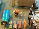
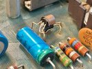
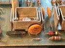
Attached are a few photos of one of the driver boards, straight out of the amp, not even cleaned yet. In addition to replacing electrolytics I’ll be testing and replacing everything else as needed. An interesting note is the small copper clip physically linking the two (differential?) transistors - presumably for better thermal tracking between them? And thoughts on why the one resistor (R135/136) is shrouded in shrink wrap? I found that odd.

A couple of additional questions for those of you with more expertise than I have:

Should I also be looking at replacing Q105/106 (the other large transistor on a heat sink?)

Are there any other obvious things/gotchas I should watch out for? I see that a lot of people replace the 3.6k 5w resistor with a higher wattage one. Again, for better management of heat issues?

More to come as I progress. Thanks again everyone, the knowledge sharing on this site is truly awesome!IMG_2846.jpegIMG_2848.jpegIMG_2847.jpegIMG_2850.jpegIMG_2849.jpeg
 
I remember those flying-saucer heatsinks being around $10/ea. from an electronic supplier back when I did the FSB several years back, I bet they’re more now!

That looks like a later board, is it a late 2105?

<edit> NM, I see your other post, late it is.
 
It’s an original board, but mine is a later production unit. From ‘73 or ‘74 I believe, don’t recall exactly.
 
Attached are a few photos of one of the driver boards, straight out of the amp, not even cleaned yet. In addition to replacing electrolytics I’ll be testing and replacing everything else as needed. An interesting note is the small copper clip physically linking the two (differential?) transistors - presumably for better thermal tracking between them? And thoughts on why the one resistor (R135/136) is shrouded in shrink wrap? I found that odd.
I like the small copper clip setup. I think that this board is a little later than mine because of that. They made many changes to this board over the long production run of these amps. Most of the changes were due to semiconductor changes as better options became available and older options went unobtainium. These changes caused some resistor value changes and possibly some other components also, so it is not just the semi's that changed. Not all changes were documented and you should check every component on the board before you make an order.
I have read that the resistor in the tube is in a position that can protect the board by blowing first under certain conditions and the sheath is to allow it to safely blow. Then again I have never heard anyone say that they needed to replace this resistor so that could just be audio-lore, but it makes sense.

I do not recall seeing that resistor on the back of the board in any picture before.

Does anyone have that on their board?? Is it factory??

The big 5W resistor should be lifted if there is any extra lead sticking out of the back of the board - you might get a mm or so - LOL. If you find it out of spec and replace it, float it off the board a bit, it does run hot.

I’ve seen mentioned here that there’s also a service bulletin for this amp (I believe relating to the driver boards.) The contact person at the factory said there were none for my amp, I’m wondering if possibly that’s because it’s a later unit? Any comments/opinions on that are appreciated.
It is not that your board is a later board. They just stopped producing replacement boards and are out of stock. They also do not carry a kit for the service bulletin any more but they do have some replacement parts (like the heatsinks etc.)

Worthwhile project for sure. Enjoy!
 
Interesting about the sheathed resistor, I agree the “lore” is somewhat logical.

Re: the 5 watt resistor, mine is already spaced a little off the board (2 - 3mm.) The board is only slightly scorched, but it’s clear that’s a hot area. Since there’s room, I think I’ll replace that with a 10 watt one as I have seen done in a number of places, spaced off the board as room will allow. No downside to this AFAICS and heat management seems to be a thing with these amps.

On that note, I plan to add some kind of active cooling with small fans to keep things more comfy inside. Nothing too fancy, just a little extra air flow.

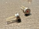
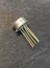
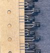
Re: the copper clipped transistors, I ordered a few replacements from Mac figuring I’d try to get two per side that I could match as close as possible (they were cheap.) McIntosh has superseded the originals with a metal can “dual” type now (which they didn’t tell me when I was ordering.) Photo below, and sorry I don’t know the correct term for this device. They’re all stamped “155” and each has a four digit number as well, which varies from one to the next. I assume a test result or something, but I hate to assume… A few of them also have what appears to be a small spacer between the leads. Anyone have thoughts on this?

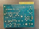
Also interesting is the resistor on the trace side of the board. One of the factory’s undocumented updates? It’s a 15k, and it’s not on the schematic. I’ve circled where it is in the circuit in the attachment below. Wondering if someone with more expertise might chime in on why they would have added this?

And the deeper I go, the curiouser it gets… The amp was sent to the factory in 2002 for a checkup. They replaced very little to get it back to spec, but the main filter caps were done then (I see evidence on the bottom chassis plate that looks like one of the originals was leaking.) The replacements are fine physically, although I’ll replace them anyway just due to age. But here’s where it gets interesting: the factory spec calls for 39000µf, 40 volt cans. McIntosh put in 30000µf, 100 volt parts. I was surprised they would go that much lower in capacity on those, it seems like it would have an impact on performance at low frequencies and high power. Wondering why they thought that was OK? Very un-McIntosh…IMG_2851.jpegIMG_2852.jpegIMG_2860.jpegIMG_2861.jpegIMG_2863.jpeg
 
On that note, I plan to add some kind of active cooling with small fans to keep things more comfy inside. Nothing too fancy, just a little extra air flow.
It should run fine without a fan unless your pushing 75+ watts per channel 24/7. Or if the location has restricted airflow.
Re: the copper clipped transistors, I ordered a few replacements from Mac figuring I’d try to get two per side that I could match as close as possible (they were cheap.) McIntosh has superseded the originals with a metal can “dual” type now (which they didn’t tell me when I was ordering.) Photo below, and sorry I don’t know the correct term for this device. They’re all stamped “155” and each has a four digit number as well, which varies from one to the next. I assume a test result or something, but I hate to assume… A few of them also have what appears to be a small spacer between the leads. Anyone have thoughts on this?
I got replacements a few years ago and they were discreet transistors - I have not used them yet but planned to thermally couple them with a small piece of copper pipe. I would be interested in any more info on these as they might be a better option. ODD that the spacer is only on some of them. Hopefully they found a better option or as good, and are not sending out some stock that they have that will due. (I guess you ordered double what you wanted since you did not know they were sending dual types)
And the deeper I go, the curiouser it gets… The amp was sent to the factory in 2002 for a checkup. They replaced very little to get it back to spec, but the main filter caps were done then (I see evidence on the bottom chassis plate that looks like one of the originals was leaking.) The replacements are fine physically, although I’ll replace them anyway just due to age. But here’s where it gets interesting: the factory spec calls for 39000µf, 40 volt cans. McIntosh put in 30000µf, 100 volt parts. I was surprised they would go that much lower in capacity on those, it seems like it would have an impact on performance at low frequencies and high power. Wondering why they thought that was OK? Very un-McIntosh…
When I was replacing those caps on mine I had a reputable dealer try to talk me into some cans of 47000mf at 100V but I really wanted to stay with the original design as much as possible. I went with 40000mf 40V but I had to wait for them. I'm sure the higher capacitance the other dealer had would have been fine - maybe better - and a little more room on the voltage would have been good too.
I do not think that a lower capacitance for the main caps is a good idea. Many people raise the capacitance as an upgrade. (more reserve for heavy bass) I have also read that the older caps leaned towards a higher capacitance than rated, so a higher cap may match the original better. (this is more 'lore' since I have not tested the theory myself)

Sometimes people have 'close enough' in stock, and when you are running a shop you need to keep turning the wheel and keeping customers happy. The nice thing about doing it yourself is that you can take your time.
Also interesting is the resistor on the trace side of the board. One of the factory’s undocumented updates? It’s a 15k, and it’s not on the schematic. I’ve circled where it is in the circuit in the attachment below. Wondering if someone with more expertise might chime in on why they would have added this?
Seems like it would lower the volume of the signal coming from the input board. Seems to me that would not be a good idea in general but it may be possible that there are some semiconductor changes in the amp that made this change beneficial. Then again - it does have gain controls so....
 
The saga continues…


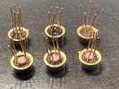
For reasons not important to this discussion, McIntosh ended up double-shipping me the differential transistors. But in the second shipment, the devices are completely different than the metal can, dual transistors they sent last week. These are the same style singles as the originals on my boards. Both parts have the same part number on the bag and invoice (it’s the number the parts department said is correct for the current, superseded part.)

So for anyone reading this, which would you use? I’ll start a second thread asking this same question.

Received today:
IMG_2872.jpeg

Received last week:
IMG_2860.jpeg
 
I’d be curious to test them and compare gain to the original pair.

Regarding power supply filter capacitors: True, people without knowledge of the design do often claim that significant increases of capacitance will somehow improve the amplifier. This is only true if the original capacitors were of insufficient capacitance, which is unlikely with a McIntosh amplifier. McIntosh didn’t build the MC2105 with a strong concern about saving costs, or the front panel would be plastic and the chassis yellow zinc. Anyway, it would be interesting to know more about exactly who replaced the original 39,000uF caps with 30,000uF caps and why. McIntosh, at least a few years ago, still stocked those capacitors so I would expect that an authorized service center would have ordered McIntosh parts, must be more to the story.

Buy capacitors as close as practical to the original 39,000uF, a little higher won’t likely hurt (or help) anything but jumping a LOT in capacitance has the potential for increasing the load on the power transformer and rectifier, and if the downstream can’t pass any additional current as far as bass etc., which is often the case, you’d be doing it for no gain.
 
Last edited:
Seems to me that the 30,000ųf values are what McIntosh currently offers to their service centers for 2105s, 2300s, etc.
 
It was the McIntosh factory that did the cap replacement, so we know the “who” part of the puzzle. I sent the amp back to the mothership in 2002 for evaluation and repairs as necessary to keep it in spec. The cans have the Mac logo on them, so they are definitely factory parts. Based on damacman’s comment, maybe this is the part they have settled on as the standard replacement for some time now?
 
I’m not going out on a very long limb when I say that it is probably more than adequate to have the two 30,000uF caps then, as McIntosh Engineering would have to approve it as a substitute part before Parts would be offering it in that application.

I would however, return it to the 39,000uF if the opportunity presents itself, simply because it might offer some improved filtration and/or reserve power, … but mostly because it is more original.
 
Update: The power supply refurb is done. All caps and resistors replaced, along with the thermistors and the diodes for the half-wave supply. Somewhat interestingly, the 50+ year old original carbon comp resistors tested within spec although a few had drifted upward a bit.

I want to test rail voltages before continuing. The driver boards are currently out of the amp, do they need to go back in before I start measurements? I read somewhere that they don’t for this purpose. The input board is still connected. I know that Mac states that the gain controls be at minimum for testing, anything else to be aware of? Do I need to connect a load for this? I won’t be sending any signal, just want to verify DC voltages before continuing.

Thanks in advance for any advice!
 
You won’t have the idle load on the power supply without the driver boards, but it harms nothing to power it up without them to check your work.
 
Back
Top Bottom