


MC2105 restore to former glory / parts list
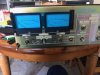
I finally decided to restore my beloved MC2105. I am a hobbyist, not an engineer so my thoughts on circuit theory are to be taken with a grain of salt. That being said: I do have some insights that may help people that don’t do this work every day.
Please!! If anyone on the forum sees any mistakes in my parts list or logic, comment and help us all learn.
My 2105 has a later serial number S# 88M11. McIntosh said it came off the line between 1971 and 1972.
I want to start with some mistakes I made:
1. I recapped the whole amp before plugging it back in and testing. It would have been better to benchmark the performance of the amp and then recap section by section and test between each step to see what improvement followed. Probably best to start with the power supply. Then the input section, output section, and finally the meter section. The amp did work great when I was finished but it would have been easier to track down a mistake if I would have tested between each section and it would have pointed out what changes yielded the most benefits.
2. I bought a kit. I hoped this would have saved me the time researching and acquiring parts, but it did not! I ended up doing the research anyway. I bought some parts that I thought would be better in some cases. Also, the parts are available and cheaper if you get them yourself. You learn more and are better prepared to install them if you pick them out yourself. Some resources are Digi-key, Mouser, Hayseed Hamfest, TTI, and Parts-express.
3. I did not put another component in my main system during the refurb. I believe my stress level would have been lower if I had put another amp in my system during the time my amp was on the bench. Music always helps! This made me want to hurry which is never a good idea. Plan on the restoration taking as much time as necessary, you may have to wait for parts or for windows of time that you are feeling focused and not distracted by other things going on in your life.
Tools: I have a soldering setup, a Digital Multimeter, an Oscilloscope, a signal generator, dummy load, small brushes and tools, and a pair of 3.5x magnification glasses from the drug store. I would like to get a THD analyzer next. A Refurbish can be done with less… and can be done better with more. Budget-budget-budget…
Doing your homework before ordering parts:
Get the paperwork. You need to find all the paperwork you can about your unit. Make sure the service manuals and schematics you get are correct for your serial number as many of the units had changes made during their production life and early units can be different from later units. HiFi engine is a great site for finding paperwork. Also, check to see if there are any service bulletins or later updates recommended by the manufacturer. I printed several copies of the schematics and board layouts so I could take notes.
Cleaning: Cleaning the unit is the best way to get to know it. Start with cleaning. Clean as you go. Clean when you are finished. Small brushes, isopropyl alcohol, Q-tips, make-up pads, electronic spray cleaners, chrome polish, wax – whatever helps you to detail the unit. You will know your way around the unit when you are done. This is also a good time to check your schematic against the actual unit.
Clean out all the controls (pots and switches). Use the right chemicals on these. I like Caig DeoxIt F5 Fader lube for most pots.
Plug it back in and test after the first clean. You may be satisfied and stop there – It makes a big difference!
Measure all the parts you want to replace. Take the amp apart and physically find all the parts you want to replace. Don’t just go by the service bulletin’s list. At the very least all electrolytic caps should be replaced. I got a small metal ruler marked in mm and measured all the parts I planned on replacing. You cannot get all the exact sizes but if you have all the sizes written on your parts list then when you start shopping online for the parts you will make better decisions. This also helps familiarize you with the locations of the parts and what they do in the circuit which is important to know for shopping also. There may be some parts that are not what the service manual says they are. Make a note of this when measuring the parts. If your unit has been working and has parts that seem original but do not match the service manual, you should in most cases replace with parts of the actual value. Changes were made during production and not all changes were documented.
Organize your list. Digi-key, Mouser and the others have a list feature on their websites. Build your list online and then check it again with the service manual before purchasing. It is a real bummer to have to order one part you missed later and wait another week for it to come in and pay more shipping. Use the comment section in the online list feature to list what board or part of the circuit the components go to. Print the list and check it twice with the unit in front of you!
Pick your parts carefully. There are many things to consider when picking parts. They should be quality, they should fit well, they should look as period as possible without sacrificing performance. You can read for weeks on capacitor choices alone and barely scratch the surface so I will speak in general terms on the subject.
Capacitors: In my opinion you should try to preserve the character of a classic unit. Using caps with a higher voltage rating is a good idea and will help you match the size of the original components but don’t go overboard. I think double the voltage rating is as far as you should go unless availability dictates more. These units do see a higher mains voltage these days and the caps will last longer with a higher voltage rating. Keep the capacitance the same to the best that is available. Upgrading parts can improve the unit but perhaps it is better to get the unit up to speck before upgrading caps to “boutique types”. If the unit had Mylar caps use the best mylar caps you can find. If there is a bi-polar electrolytic in the signal path replace it with the same. It is tempting to make “improvements” while you are inside the unit but don’t change component types until you get to benchmark the amp after a basic restore. Some may disagree but if it is your gear then you have time to open it up again later. It’s part of the fun anyway.
Resistors: In my amp there were mostly ½ Watt carbon comp resistors. I checked them all. Any that were marked as 5% on the schematic or out of tolerance got replaced. I used ½ Watt carbon film. I chose this type for a few reasons. Carbon film are physically larger than the metal film resistors so I did not have to go up in Wattage to achieve a classic look. They typically can handle higher voltages than metal film and are closer to the older design speck. They will not change the overall sound character or aesthetic look of the amp. Carbon film are an upgrade from the carbon comp resistors, and will be tighter tolerance, last longer, and are quieter. A very conservative upgrade that I thought would be ok for round one.
**I also wanted to have some continuity in the type of resistors, so I found a ‘series’ of resistors from the same manufacturer that had most of the values that I needed when shopping online. This made the bulk of my replacements the same size and look and value marking scheme.
I would have needed 2W Metal film to match the size of most of the original resistors. Although going up in wattage is generally considered fine to do, I believe that going up too much will take a problem that might just burn a resistor and turn it into a problem that will burn more parts.
I used 5% or better for all the resistors I changed. Some 5% resistors I went to 1% based on where they were in the circuit.
Some higher W resistors in the unit were replaced also and I matched them the best I could with all these factors in mind.
If they were wire wound resistors I did not ‘upgrade’ to non-inductive types as the inductance could be part of the circuit design (on purpose or accidentally). I have read that non-inductive wire wound resistors in the MC2105 could cause oscillation in the output section.
Thermistors: My amp’s thermistors were totally worn out and I replaced them. I suggest replacing them if your unit uses them as a soft start like the MC2105. My amp would dim the lights in the house when I turned it on! This cured the problem.
Transistors: The transistors in my 2105 were all working well. I will probably go back in and test the input board for distortion and revisit the transistors on that board. I may change them, and I may not. I need to tool up a little more to be able to properly test the amp for THD and match transistors so that will have to wait.
Diodes: I did not change any diodes in my amp but may revisit this in the future. I did order D103,104 from McIntosh in case I do the update to the output board.
General: All this is to say that when I choose parts for a refurb, the factors I care about are as follows:
Type and value, Quality, Fit, Aesthetic vintage look, Availability.
**All parts replaced in one channel (right or left) are matched on the other channel.
**Check any Voltages that you can after the work is done – Test your THD if you have the capability – calibrate the meters – replace the lamps.
Upgrades/Mods: I decided to leave all modifications and upgrades for later (if ever). After I have returned the unit to ‘like new’ status and have benchmarked what that looks like (sounds like), I can better decide if I want to go further.
There is a bulletin from McIntosh on this unit to upgrade the output boards. I got all the parts to do the upgrade but decided to leave this for later. Once again, I want to benchmark before I upgrade (or update in this case).
In the end I replaced all the electrolytic capacitors, left the mica capacitors alone, and changed all resistors that were out of tolerance and a few that I thought were in places in the circuit that were important like the bias resistors for some of the transistors. I also calibrated the meters and changed all the lamps with original type incandescent lamps. The strips of foam around the meters behind the glass I replaced with thick felt cut into strips as I did not want to use foam that will deteriorate. The parts I did not use went into a box with all the paperwork and notes for the next time I work on the amp.
The amp is working great and sounds better than it has in years!! I can’t believe the difference. All the clichés are true – tighter bass, better sound stage, high end detail, vocal warmth and clarity, more musical… ….
Please see the parts list I attached to the post. I hope the list helps. Enjoy your projects.
I finally decided to restore my beloved MC2105. I am a hobbyist, not an engineer so my thoughts on circuit theory are to be taken with a grain of salt. That being said: I do have some insights that may help people that don’t do this work every day.
Please!! If anyone on the forum sees any mistakes in my parts list or logic, comment and help us all learn.
My 2105 has a later serial number S# 88M11. McIntosh said it came off the line between 1971 and 1972.
I want to start with some mistakes I made:
1. I recapped the whole amp before plugging it back in and testing. It would have been better to benchmark the performance of the amp and then recap section by section and test between each step to see what improvement followed. Probably best to start with the power supply. Then the input section, output section, and finally the meter section. The amp did work great when I was finished but it would have been easier to track down a mistake if I would have tested between each section and it would have pointed out what changes yielded the most benefits.
2. I bought a kit. I hoped this would have saved me the time researching and acquiring parts, but it did not! I ended up doing the research anyway. I bought some parts that I thought would be better in some cases. Also, the parts are available and cheaper if you get them yourself. You learn more and are better prepared to install them if you pick them out yourself. Some resources are Digi-key, Mouser, Hayseed Hamfest, TTI, and Parts-express.
3. I did not put another component in my main system during the refurb. I believe my stress level would have been lower if I had put another amp in my system during the time my amp was on the bench. Music always helps! This made me want to hurry which is never a good idea. Plan on the restoration taking as much time as necessary, you may have to wait for parts or for windows of time that you are feeling focused and not distracted by other things going on in your life.
Tools: I have a soldering setup, a Digital Multimeter, an Oscilloscope, a signal generator, dummy load, small brushes and tools, and a pair of 3.5x magnification glasses from the drug store. I would like to get a THD analyzer next. A Refurbish can be done with less… and can be done better with more. Budget-budget-budget…
Doing your homework before ordering parts:
Get the paperwork. You need to find all the paperwork you can about your unit. Make sure the service manuals and schematics you get are correct for your serial number as many of the units had changes made during their production life and early units can be different from later units. HiFi engine is a great site for finding paperwork. Also, check to see if there are any service bulletins or later updates recommended by the manufacturer. I printed several copies of the schematics and board layouts so I could take notes.
Cleaning: Cleaning the unit is the best way to get to know it. Start with cleaning. Clean as you go. Clean when you are finished. Small brushes, isopropyl alcohol, Q-tips, make-up pads, electronic spray cleaners, chrome polish, wax – whatever helps you to detail the unit. You will know your way around the unit when you are done. This is also a good time to check your schematic against the actual unit.
Clean out all the controls (pots and switches). Use the right chemicals on these. I like Caig DeoxIt F5 Fader lube for most pots.
Plug it back in and test after the first clean. You may be satisfied and stop there – It makes a big difference!
Measure all the parts you want to replace. Take the amp apart and physically find all the parts you want to replace. Don’t just go by the service bulletin’s list. At the very least all electrolytic caps should be replaced. I got a small metal ruler marked in mm and measured all the parts I planned on replacing. You cannot get all the exact sizes but if you have all the sizes written on your parts list then when you start shopping online for the parts you will make better decisions. This also helps familiarize you with the locations of the parts and what they do in the circuit which is important to know for shopping also. There may be some parts that are not what the service manual says they are. Make a note of this when measuring the parts. If your unit has been working and has parts that seem original but do not match the service manual, you should in most cases replace with parts of the actual value. Changes were made during production and not all changes were documented.
Organize your list. Digi-key, Mouser and the others have a list feature on their websites. Build your list online and then check it again with the service manual before purchasing. It is a real bummer to have to order one part you missed later and wait another week for it to come in and pay more shipping. Use the comment section in the online list feature to list what board or part of the circuit the components go to. Print the list and check it twice with the unit in front of you!
Pick your parts carefully. There are many things to consider when picking parts. They should be quality, they should fit well, they should look as period as possible without sacrificing performance. You can read for weeks on capacitor choices alone and barely scratch the surface so I will speak in general terms on the subject.
Capacitors: In my opinion you should try to preserve the character of a classic unit. Using caps with a higher voltage rating is a good idea and will help you match the size of the original components but don’t go overboard. I think double the voltage rating is as far as you should go unless availability dictates more. These units do see a higher mains voltage these days and the caps will last longer with a higher voltage rating. Keep the capacitance the same to the best that is available. Upgrading parts can improve the unit but perhaps it is better to get the unit up to speck before upgrading caps to “boutique types”. If the unit had Mylar caps use the best mylar caps you can find. If there is a bi-polar electrolytic in the signal path replace it with the same. It is tempting to make “improvements” while you are inside the unit but don’t change component types until you get to benchmark the amp after a basic restore. Some may disagree but if it is your gear then you have time to open it up again later. It’s part of the fun anyway.
Resistors: In my amp there were mostly ½ Watt carbon comp resistors. I checked them all. Any that were marked as 5% on the schematic or out of tolerance got replaced. I used ½ Watt carbon film. I chose this type for a few reasons. Carbon film are physically larger than the metal film resistors so I did not have to go up in Wattage to achieve a classic look. They typically can handle higher voltages than metal film and are closer to the older design speck. They will not change the overall sound character or aesthetic look of the amp. Carbon film are an upgrade from the carbon comp resistors, and will be tighter tolerance, last longer, and are quieter. A very conservative upgrade that I thought would be ok for round one.
**I also wanted to have some continuity in the type of resistors, so I found a ‘series’ of resistors from the same manufacturer that had most of the values that I needed when shopping online. This made the bulk of my replacements the same size and look and value marking scheme.
I would have needed 2W Metal film to match the size of most of the original resistors. Although going up in wattage is generally considered fine to do, I believe that going up too much will take a problem that might just burn a resistor and turn it into a problem that will burn more parts.
I used 5% or better for all the resistors I changed. Some 5% resistors I went to 1% based on where they were in the circuit.
Some higher W resistors in the unit were replaced also and I matched them the best I could with all these factors in mind.
If they were wire wound resistors I did not ‘upgrade’ to non-inductive types as the inductance could be part of the circuit design (on purpose or accidentally). I have read that non-inductive wire wound resistors in the MC2105 could cause oscillation in the output section.
Thermistors: My amp’s thermistors were totally worn out and I replaced them. I suggest replacing them if your unit uses them as a soft start like the MC2105. My amp would dim the lights in the house when I turned it on! This cured the problem.
Transistors: The transistors in my 2105 were all working well. I will probably go back in and test the input board for distortion and revisit the transistors on that board. I may change them, and I may not. I need to tool up a little more to be able to properly test the amp for THD and match transistors so that will have to wait.
Diodes: I did not change any diodes in my amp but may revisit this in the future. I did order D103,104 from McIntosh in case I do the update to the output board.
General: All this is to say that when I choose parts for a refurb, the factors I care about are as follows:
Type and value, Quality, Fit, Aesthetic vintage look, Availability.
**All parts replaced in one channel (right or left) are matched on the other channel.
**Check any Voltages that you can after the work is done – Test your THD if you have the capability – calibrate the meters – replace the lamps.
Upgrades/Mods: I decided to leave all modifications and upgrades for later (if ever). After I have returned the unit to ‘like new’ status and have benchmarked what that looks like (sounds like), I can better decide if I want to go further.
There is a bulletin from McIntosh on this unit to upgrade the output boards. I got all the parts to do the upgrade but decided to leave this for later. Once again, I want to benchmark before I upgrade (or update in this case).
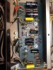
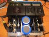
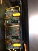
In the end I replaced all the electrolytic capacitors, left the mica capacitors alone, and changed all resistors that were out of tolerance and a few that I thought were in places in the circuit that were important like the bias resistors for some of the transistors. I also calibrated the meters and changed all the lamps with original type incandescent lamps. The strips of foam around the meters behind the glass I replaced with thick felt cut into strips as I did not want to use foam that will deteriorate. The parts I did not use went into a box with all the paperwork and notes for the next time I work on the amp.
The amp is working great and sounds better than it has in years!! I can’t believe the difference. All the clichés are true – tighter bass, better sound stage, high end detail, vocal warmth and clarity, more musical… ….
Please see the parts list I attached to the post. I hope the list helps. Enjoy your projects.


