• The move to the new server is done. There are some software and database maintenance updates in process. This has us passing the hat around to help out. We appreciate any donations. Seriously, even a dollar helps. The payment page may be found here - https://www.audiokarma.org/support.html

MC2125 with bad Drivers

Ok Ive calmed down. I apologize for the snark remark. Thanks everybody. Now I have many options for the predrivers. Back to one of my original questions. I think when I replaced Q224 132-136 with MPSA42 I should have also replaced its partner Q20 132-150 with MPSA55. Is it possible that just replacing the one transistor drove the right channel into oscillation killing the driver transistors? Should theese transistors be replaced in pairs? Should I go ahead and replace Q220 132-50 with MPSA55 or leave original?
 
Last edited:
Q224 and its compliment Q226 are not in the audio circuit. They are part of the protection circuit. Wait for your reply.
 
When the Voltage at the base of Q224 goes high enough to turn on (from + current sense) collector current flows from B++ through R246 and R2666. The Voltage at the base of transistor Q220 goes low enough to turn on because of the Voltage drop across R246. This pulls up the Voltage at the collector of Q214 that works against the collector tied to R264 reducing the output drive to prevent overload. A properly working board could be seen with a scope at the + and - drive points. A dual trace scope would be nice. I have an idea of what kills the drivers. Ya dig?
 
I have a dual scope. I am very curious at what you think might kill the drivers. If the voltage at base of Q224 goes high enough to turn on (from + current sense) then would it be possible that the + current sense was so high that it shorted Q224? and if that is the case what is causing + current to be that high?
 
The Voltage would not go high enough to damage the transistors if the resistor network was correctly in place. As far as the drivers, did they fail as a short, open, or little or no gain. To tell you the truth, the Fairchild PNP drivers were found to die of old age. I recently went through two 2205s and one was so weak it couldn't pick up a starving whore on an LA freeway at 4:00 am. Sure, it worked, but that was the issue. Remember, transistors are current devices. Let me know if you know the failure mode of your devices.
 
Fairchild PNP is short base to emitter to collector.
RCA NPN now tests fine (HFE 41). WTF
Testing on Atlas DCA55
 
The Fairchild PNP may be victim of old age also where the insulator oxide layer breaks down causing the short. I do not think it is tin migration from the case.

That is why you need to be careful of using old semiconductor devices, especially the power devices. They should be tested carefully and put under load to make certain they perform as required. You could make a simple circuit to test them for current gain at an Amp or two, levels higher than uA or mA exceeding your Atlas tester. A heat sink would be in order. Funny about the RCA device. I have seen and heard similar stories when testing radio frequency NPN power transistors with the smaller component testers.

To the unknowing, they can be a costly mistake. For the pocketbook, they can be worse than the mythical “fool’s gold”. The mistake not only costs time and money but also erode trust, reputation, and opportunities. One's man's junk is just what it is. You do not need to dig any further.

Limp celery won't make the best tuna salad, even bathing overnight in a Viagra bath. Old parts are just what they are. Caveat emptor.
 
I have posted your board on top with a board I did last year on the bottom. There are some slight differences on the left side (output) of the circuit board that will control any parasitic oscillation from occurring with the amplifier and eliminate the need for the inductive wire wound resistors in the output power section. We can get to that later once we straighten out your current needs.

 
I have posted your board on top with a board I did last year on the bottom. There are some slight differences on the left side (output) of the circuit board that will control any parasitic oscillation from occurring with the amplifier and eliminate the need for the inductive wire wound resistors in the output power section. We can get to that later once we straighten out your current needs.
I see you have replaced some of the ceramic caps, 2 of the film caps for polystyrene types, and the 2 polystyrene types by the potentiometer for film.
 
I replaced the Fairchild driver with MJ15021. I replaced the output drivers with MJ15004 and MJ15003. Passed dim bulb. Hooked up to mains clean signal. Limiter kicks in at 162 watts with a 1k sine wave. I don't see any oscillation (although Im not sure what it would look like) tested frequency up to 20k.
Im gonna set the bias next. Put the amp on a Variac to get exactly 120V and use a killowatt.
 
After turning pots fully CCW I increased one until a increase of .05amps then the other for a increase of .05amps. Im sitting idle at 0.328amps

Thats a bit low of the estimated .4amps in the service manual.
 
I see you have replaced some of the ceramic caps, 2 of the film caps for polystyrene types, and the 2 polystyrene types by the potentiometer for film.

It is a little more than replacing capacitors. Depending on the circuit board, some circuit paths are added, the reason for the two black jumpers on top. I think there is one more change also. It appears you have it going now! That is great.
 
This is what you will need. The last service manual for the MC2205 I am aware of so I can explain to you what changes were made in the end.

Perhaps Patrice can make this manual available to you and others in the database here on Audiokarma. I posted the last two McIntosh Semiconductor Data information because I thought it would help others. Now it is the others turn to return the favor to us who enjoy McIntosh. See if you can obtain a copy. We can then discuss the modifications.

I don't know if many knew of the later pc board designs and the service manual for them. Be patient. Let's see what others say. I do this as a hobby, not a livelihood. I also like to listen to my system as I am doing now.

I have a copy if needed.


1778105493666.png1778105778343.png
 
Later driver pcb produced is 045-557

Real driver transistors for MC2205 are for 132-151 (blue dot ) r by 132-230 = MJ15019 PNP type and for 132-152 ( violet/Red dot ) replaced by 132-229 = MJ15018 NPN

Patrice
 
Later driver pcb produced is 045-557

Real driver transistors for MC2205 are for 132-151 (blue dot ) r by 132-230 = MJ15019 PNP type and for 132-152 ( violet/Red dot ) replaced by 132-229 = MJ15018 NPN

Patrice
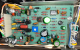
Later driver pcb produced is 045-557

Real driver transistors for MC2205 are for 132-151 (blue dot ) r by 132-230 = MJ15019 PNP type and for 132-152 ( violet/Red dot ) replaced by 132-229 = MJ15018 NPN

Patrice

Patrice, in case you did not have the schematic of the 045-557 pc board I am including it here. Semiconductor devices that are no longer available do not help anyone on the forum. A number of us have given members useful information that will help them do the required repair today, with parts that compliment or exceed the operational characteristics required for the device, especially those archaic driver transistors.

1778167068105.png
 
Back
Top Bottom
