• The move to the new server is done. There are some software and database maintenance updates in process. This has us passing the hat around to help out. We appreciate any donations. Seriously, even a dollar helps. The payment page may be found here - https://www.audiokarma.org/support.html

MC250 burnout

MarkDG

New Member
I have had a McIntosh MC250 for years and it worked beautifully until it went up in smoke several years ago. I have finally gotten around to see what was burned out -- and I have to say I'm surprised at the damage. The right channel has lost all transistors (except one) and many resistors are charred or split. Even the wirewound resistors are shot. The wiring on the heat sinks have all insulation burned off. One power supply resistor is split.
I guess my question is -- what would cause such destruction?? The speakers they were hooked up to were AR1, still in use with a different amp.
I will comment further as I get more into this, but any thoughts or comments would be most helpful.
 
Register to hide this ad
Hopefully, and most likely the transformers are all okay. I would start with testing the transformers however, because it might be a long process if you need to find new ones.

Was someone there to shut it down quickly when it went supernova? If not then I'm not surprised at the damage.

It will take a fair amount of investigating to determine the cause of your cascading / catastrophic failure, unless someone like Patrice weighs in and has seen identical failures. Unless you have the time and skills to do the forensic work, I would start with testing the important parts and rebuild everything else.

Is "lost all transistors" from testing or from smoke on them / appearance? How are the circuit boards?

The reason that your speakers are still fine is by design, the channel probably shorted or "railed", putting DC into the output tranformer, which creates no speaker output from its secondary winding.

Best of luck and welcome to AK.
 
Thanks for all the welcomes. I'm a retired musician who has used electronics extensively, and "fixed" them as well as I can. I can read a schematic but my understanding of how things work is a bit thin. I have been staring at this for hours, and trying to guess what might have happened.

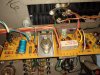
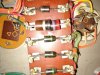
In the PS, R115 is in two pieces, which feeds the -40 filtered line. C57 is out of spec as one might imagine after all these years, but not likely a cause of any problem. The one interesting thing is the lack of solder on the joint (circled in the picture if I can figure out how to load it) and the rather loose wire there (on C57). It had to have come from the factory that way. Could an intermittent connection there be part of the problem?

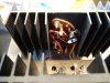
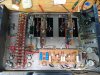
The left channel is all OK as far as I can tell. I checked one output transistor and it's OK. The right channel however is toast. I checked all transistors with a meter and they are all dead except Q18. They look OK visually and the circuit board is good -- the only obvious burn-outs are the resistors. The picture of the Circuit board shows 3 burned out resistors (really all of them are in half). The main heatsink is where the resistors are not even recognizable, and the transistor sockets and wire insulation have melted. Probably the thermal shut-down stopped it from doing more.

I've been trying to measure all of the resistors, but think that maybe replacing all of them is the best. Some difficulties are with the revisions McIntosh has made -- the serial number is 24L57, so I downloaded the closest schematic I could find, which lists some changes. It says that R88, 89, 90, 91 are used, but the values of 2200W on R50 (what does that W mean??) is not what I have. I have 220, checked by color and meter. (The colors are pretty bad due to overheating.) Also R34 should be 3.3K rather than 33k. For these two , I also checked the good left channel board to make sure I'm correct.

I will check the transformer as was suggested, and have meter-checked the PS diodes -- they all seem OK. I'll recap everything if it seems that I can resurrect this, except for the 9300's which I think are OK.

Has anyone ever had a problem with the output transformers? I have no idea how to even check them out!

Thanks to anyone who has any ideas. I'd like to get this amp back running.
PS-resistor.jpg Heatsink.jpeg RT channel board.jpeg
 
Thanks for the pic's, looks like a candidate for Audio Classics, they went thru mine and wasn't that expensive, good for another few decades now and sounds great. Give Ryan a call there if interested. Best of luck! AL
 
Hello MarkDG

Welcome on AK !

Yes , as Jeff said I already saw this kind of damages .
You have to understand that this is a big job to rebuilt your amplifier .
Thank you for the pictures but we miss the back of the driver pcb
I am pretty sure that the both transistors (yellow dot 132-021 and orange dot 132-032 ) are dead . Perfect substitutes still exist today .
Testing "output transformers" is very easy with audio signal generator , oscilloscope and dummy load but on the working channel only . You have to disconnect all the power supply who goes on the burned channel .
Then you can disconnect the input of the "auto-former" (grey wire) of the burned channel and connect it to the working channel (in fact you will have one working channel with the "auto-former" coming from the burned channel) and you can be sure about his perfect working order .
One "auto-former" is very expensive and it will be a good idea to start by this test to know if this repair will be expensive or not.
Never use your amplifier without any load at the output .
You can ship it to AUDIOCLASSICS in NY of course and RYAN knows perfectly what to do .
This will be more expensive than if you do it yourself but do you know how to do it and do you have all the necessary tools ?

PATRICE
 
Last edited:
Thanks Patrice.

It will involve a bit of work, but that has never bothered me. I take my time and understand what I am doing before I do anything, especially something I am not completely proficient with. I learn a lot that way. I also ask a lot of questions!

The burned channel is no longer in the chassis -- that is the PCB and the two heat sinks. I will check the power trans first, hopefully that should be OK. (I have to find one resistor for the PS.) At that point, if I wire in the left channel I should have a mono amp. Then switch the auto-formers to see if the right one is OK. Of course, if it is not, then I may have some problems, but I will at least be there to stop things, unlike when it blew in the first place.

Main question: Should I do a "soft start", ie Variac or dim bulb, for the sake of the PS. Or is that not smart or necessary with this kind of circuit? It has not been powered up since it blew about about 13 years ago.

I will have to get some parts to even start -- used to have a Fry's nearby to pick stuff up, now it all has to be done by mail. So it will be a few days before I get more done on this.

Again, thanks for your help.

Mark
 
Hello

Yes a variac with an Ampmeter in serie to watch if there is something wrong when you increase the AC voltage
The pages that Jeff send are really helpfull for you
Follow instructions
 
Thank you Jeff for all of that. It is most helpful. I have a Variac and will be able to start this as soon as I get a few parts for the PS.

Mark
 
Hello all,

So far so good. I have replaced burned out PS parts, and have slowly powered it up using a Variac. Though I don't have a VTVM (do they make those anymore??), I was able to monitor the output voltage, and although it wasn't exactly what was listed in the McIntosh Service Bulletin, it wasn't bad. Output voltage stayed low and dropped negative after about 50volts, but no smoke, no heat, no apparent problems. I was able to play music through the left channel (the right is not even in the chassis) and it seemed OK. I changed the wiring to use the right autoformer and the results were the same, so the autoformer seems to be good. That was my biggest concern. I didn't do any voltage checks yet since I'm only using the left channel, and I doubt that the numbers would not be exactly right. Also, I need to replace the 4-cap capacitor, and that should improve readings. Meanwhile, I've gotten a bunch of new components to rebuild the right channel outboard board, so I will start working on that. Thanks for your comments and suggestions, and I will let you know how things go.

A note: in the MC250 schematic notes for ser no after 23L48, there are several errors. The second line of item 5 should read, "R49 & R50 are 220 ohm; R86 & R87 are 160 ohm, and R33 & R34 are 3.3k ohm". These can be verified by checking the schematics for the very similar MC2505 and also checking the resistors taken out of the amp.

Mark
 
Great update Mark, thanks.

We should have mentioned that there are notes such as schematic errors etc. in the McIntosh, hints and kinks sticky at the top of the McIntosh forum. If the errors that you noted are not already there, please add themn.
 
I've started to work on the Rt channel power output PCB, and in testing it looks the wirewounds are OK. But, the reading I get for what's called the "reference diode" is way off -- D2 (070-046) reads OL and .490, rather than OL and 1.135. (R46 was burned in two, and that was connected directly to D2.) I understand that they are near impossible to find, but that you can use two 1N4148 diodes in series to make it work -- is that likely my only option with this??

Mark
 
070-046 is a Motorola MZ2361 screened for McIntosh. In the 2100/2105/2300 it is used to reduce output as temperatures climb and protect from thermal runaway. If the same in the 250/2505 then it is important to use the correct part, the 1N4148 will make the amplifier operate, but will not protect it.
 
Hi Jeff

I do understand that -- I'm just wondering what to do if I can't find one that works. I did locate and order a MZ2361 -- we'll see if it passes muster when I get it. But it certainly will not have been screened for McIntosh.

Mark
 
Finally got my MZ2361 from a place in London -- it got to Chicago customs in 2 days, sat there for 10 more, then went to New York before coming back to the Chicago area and finally to me. But I put it in, and finished the right channel power output board and it works! I took my time with the Variac and got it up and running and let it burn in for an hour -- both channels are working and are getting to sound pretty much the same. Voltage readings are a bit on the low side though within 10 percent, so I will finish recapping the PS, and also the electrolytics on the input board before I put it through it's paces. Everything runs cool except for R43 and 44, which I think is normal. They must be set away from the board for that reason. Will update more when I install the rest of the parts. Thanks to everyone for their suggestions and help.

Mark
 
Have finished most of the work and have had it up and running -- all OK so far. The speakers I'm using aren't very even, so I have to attach it to my old AR speakers I have (original, I guess you would call them AR1), or Klipsch Heresy (early model), or Advent (NLA). I'm curious to see which speakers sound the best with it.
I did wind up ordering the can from Hayseed Hamfest -- it seemed to be a better solution rather than try to restuff it with 4 caps. I replaced the input board C51 and C52 caps with Elna Silmic II, and was ready to do the same for C53 & 54. Surprise! They had bi-polars in place, even though the schematic shows polars. There must be a reason for it, so I will order Nichicon Muse bi-polars for it. In addition, C55 & 56 are listed as being 640mfd, but 680 is what was in place. So I did replace with new 680 caps.
The only other thing I am waiting for is a replacement transistor for Q16. I was unable to get Q16 and Q18 from the same manufacturer, and since they are complementary, I thought it best to at least get them from the same maker. Maybe it won't make any difference, but those parts are really cheap. I'm using the MPSA06/MPSA56 pair.
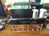
I will probably use the MC250 in the Haupwerk organ that I use for practice. The AR speakers do well for that, even though they have little treble. I use a pair of Alesis near field monitors to provide the top. My next project will be to rebuild the Pilot Preamp that I've used with the 250 for many years. The tube preamp with the 250 really can give a sweet sound!

MarkRepaired-undercarriage.jpg MC250-&-Pilot.jpg
 
Back
Top Bottom