• The move to the new server is done. There are some software and database maintenance updates in process. This has us passing the hat around to help out. We appreciate any donations. Seriously, even a dollar helps. The payment page may be found here - https://www.audiokarma.org/support.html

MC2505 catastrophe

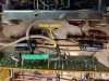
Also what is the green-shrink wrapped component on the back of the input board? Is that factory installed — or an aftermarket? I’m not saying that is your issue. Also looks like there is a diode on the back of the input board. Not sure if that is factory installed or aftermarket. Looks like that diode was spliced in to an existing lead? Probably from the 1996 repair. These are just observations —probably not related to your issue.
 
Last edited:
ok, a lot of great information and suggestions here Monk, can't tell you how much I appreciate it. And thanks SaturationPt for suggesting a DBT, I've read about these but never had a use for one, looks like I do now. I am no expert but do have some basic abilities in troubleshooting and simple repairs (e.g. replacing a pot). You've given me a lot to chew on and I will try some of the steps before throwing in the towel and sending the amp in the shop.

A few preliminary answers:
- 120Hz tone does sound similar to what I heard; have not tried headphones.
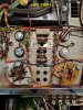
1. I added a pic of the meter board below; I can see no evidence of leakage or any burn marks.
2. speaker terminals / screws look ok, nothing out of place or touching where it shouldn't.
3. the amp is housed in the matching wood case w/panlocs so there should be no issue with long screws touching the chassis.
4. have not deoxited them yet, however hum is present even when nothing is connected to the RCA jacks.
5. cables appear good, no issues when used with other gear.
6. visually, speaker switch and circuitry looks ok. I did note however when I turned on the amp yesterday that the hum goes away when the spkr switch is turned off. VUs still peg to max.

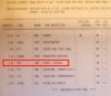
Btw, I can confirm the amp was sold in Toronto in Nov 1968, as I have the original bill of sale and all the documentation that came with the amp when it was sold. It's a beautiful piece and I also have an equally nice, matching MX112 that was bought with it at the same time so it's definitely getting repaired. I've posted below a portion of the repair bill, it shows that the following was replaced in '96: 2 x pots; glass faceplate; 4 x transistors; 4 x diodes; 8 x caps; RCA terminals; speaker terminals; power cord.

View attachment 2870201

View attachment 2870204

View attachment 2870205
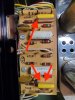
Those two Mullard Tropical Fish caps on the meter board do have "burn" marks. I don't think this is your issue, but the epoxy is stressed from heat. Generally, it's a good idea to replace Tropical Fish as the epoxy is known to be defective and can let in moisture from humid air. If you do a full restoration at some point, I would replace those.

The second photo below shows the Tropical Fish cap I removed from my meter board and it had heat stress in the exact same spot as yours.

I replaced the defective Tropical Fish with Cornell Dublier 474MSR250K

https://www.mouser.com/ProductDetail/CDE-Illinois-Capacitor/474MSR250K?qs=3tP%2BN51vMXfiwgJzbek5TA==&countryCode=US&currencyCode=USD

Those white Mallory electrolytics should be replaced at some point as well. They usually drift high over time. Mine were 150% of rated value.

Looking at that invoice, the shop that did your repair in the 90s appeared to charge for eight new capacitors, but I only see they installed four caps (two black caps behind the input board and one cap on each of the driver boards).

Is that a local Toronto shop that's still in business? It's 27 years ago, so water under the bridge but I would certainly think twice about taking anything to that shop for repair. I'm suspicious the shop might have padded the bill (i.e. charge for components and work not installed and/or performed). And it would be interesting to see if any other component quantities and labor billed on the invoice don't match the actual quantities installed...

Based on the 1996 invoice, it appears the shop installed two aftermarket speaker terminal blocks. Some MC2505 owners have reported loud hum issues with shorted terminal block screws. Sometimes the aftermarket stuff has different length screws which can be a problem as they touch something in the amp they shouldn't. I would look at those two terminals and screws very carefully...

Did you change anything between the last time the amp worked OK and when it failed? For example, did you unscrew or tighten any speaker cables at the terminal blocks?

20230426_051155.jpg

IMG_8681 Large.jpeg
 
Last edited:
Lots to look into, many thanks to all once again. I'm away right now so can't take a closer look but will spend some time on it this weekend and try to knock some things off and investigate further.

To answer some of your questions, Monk: you are correct on all fronts, in that the speakers were physically disconnected, the hum came from the amp (can't tell exactly from where as the amp was in its case inside a cabinet), and the hum went away with the spkr switch to off while VUs were still maxxed.
 
If the hum goes away when the speaker switch is off, it sounds to me like you've got an issue in the supply or on one or the other heatsinks and you're getting voltage on the outputs. The speaker switch closed provides a path for that to ground through the output transformers and I'm thinking the load will cause the supply to strain which might cause the audible hum. Headphones would give you an idea what's going on, but keep in mind that they would see some voltage they shouldn't see if there is an issue there. Better to check it with test equipment.

The meter signals are tapped off the output before the speaker switch, so any funky voltages on the output will drive the meters to their limit and will still do so if the speaker switch is opened.

Best way to check it out is to check all the diodes/transistors/caps you can powered off, then bring it up on a variac along with a current limiting device so you can let the voltages start to build and check things out without exposing the unit to a ton of current if something is shorted.

Good luck!
Much appreciated, Bob. Some of the suggested steps are beyond my skills / necessitate testing equipment I don't have, however will try to do as much as I can on the weekend and will report back. It's likely that my amp will end up going to the shop, but I want to give it my best shot first. AK is the best!
 
It would. I'd be more comfortable with a DBT as the DBT limits current and the variac does not.

I almost never use my variac but use the DBT every time I do a restoration or repair. It is easy to build, you're simply putting a light socket in series between a power cord and an outlet, think of it as interrupting the hot side of an extension cord with a light socket, and the wattage of the light bulb can be varied to work with different amplifiers etc. I built a complex one with multiple sockets, bulbs, switches, outlets, metal boxes for around $60 so a simple one is probably closer to $20.
 
What kind of hum from the preamp could be amplified and become audible from the amp itself (not speakers)?

If the hum came from either an internal fault or the source and was very high in voltage at the outputs, the autoformers might physically hum similarly to the way a power supply transformer might if drawing a lot of current. When OP turned the speaker switch to off the switch disconnected the autoformers (per the schematic) and also the hum from the amp stopped.

Anyway, OP is getting tons of good advice as is usually the case in this forum.
 
It would. I'd be more comfortable with a DBT as the DBT limits current and the variac does not.

I almost never use my variac but use the DBT every time I do a restoration or repair. It is easy to build, you're simply putting a light socket in series between a power cord and an outlet, think of it as interrupting the hot side of an extension cord with a light socket, and the wattage of the light bulb can be varied to work with different amplifiers etc. I built a complex one with multiple sockets, bulbs, switches, outlets, metal boxes for around $60 so a simple one is probably closer to $20.
Thanks for the advice Jeff. I actually thought a variac was a more sophisticated DBT, but based on your comments the two devices do different things. I will read up on both and may build a DBT, it seems simple enough.

For this weekend I will start by troubleshooting what I can with the power off as per previous suggestions, then if that doesn't yield results I will see if I feel bold enough to move on to working on the amp while powered on. I'm somewhat leery of doing that as I don't want to screw things up even worse than they are.
 
@Benz check your fuse and make sure it is the correct factory value. That 1996 repair shop seems kind of shady…
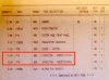
Thanks Monk, will check that, too. Btw, the shop in question is still in business today so I would assume they are reasonably honest. That said I don't have personal experience with them as they are 400km+ away from me. Someone previously mentioned that the amp only appears to have had 4 caps replaced vs. the bill showing 8 being replaced. I was thinking that perhaps the "missing" 4 caps went into one or two cans? Just guessing.
 
Thanks Monk, will check that, too. Btw, the shop in question is still in business today so I would assume they are reasonably honest. That said I don't have personal experience with them as they are 400km+ away from me. Someone previously mentioned that the amp only appears to have had 4 caps replaced vs. the bill showing 8 being replaced. I was thinking that perhaps the "missing" 4 caps went into one or two cans? Just guessing.

Take a look at the multi can that has 4 sections and the single section FP can next to it and see if either were restuffed. Look for dremel cut marks and glue or tape at the base.

I’m skeptical either of the two FP cans were restuffed. The 1996 invoice lists only two capacitor manufacturer part numbers and four quantity of each part number, totaling 8 capacitors.

ca.jpg

The multi can is an 80-80-150-50 uF. And I think the other FP can is a 500 uF.

CE and Hayseed sell replacement multi cans. Or you can restuff or just put miniatures under the chassis using terminal strips.

The CE can will look more like the original can than the Hayseed because CE purchased the Mallory FP tooling. But the Hayseed can has a higher temp rating. 85C vs 105C. Hayseed uses discreet Nichicon or Chemi-con Japanese high quality miniatures whereas CE uses the vintage style toilet roll construction.

https://www.tubesandmore.com/products/capacitor-ce-mfg-250-v-150808050-f

https://hayseedhamfest.com/products/mcintosh-amp

If it was me, I would see if there is enough space to install 5 axial or radial caps under the chassis on terminal strips or a turret board, disconnect the two original FP cans but leave them bolted on the chassis for cosmetics.

For the larger 9300uf cans, you can get 15,000uf exact size replacements from McIntosh parts dept.

By the way, these are the only four capacitors that appear to have been replaced by the repair shop in 1996. Where are the other four capacitors they charged to install?

20230425_181052.jpg

20230425_181040.jpg

20230425_181034.jpg
 
Last edited:
The repair shop charged for 4 quantity Zener diodes. I only see that they spliced one new diode to the lead of an original.

Maybe the shop replaced three other diodes elsewhere, but I don't see this in your photos...

diode.jpg

20230425_181052-2.jpg
 
Last edited:
It looks like the MAC factory changed the values of at least one of the two FP cans during later years. The later MC2505-2 don't have as many multi-sections as your picture shows.

Try and track down the correct service manual for your early version based on your serial number. Since yours is from 1968, you might have a "version 1". I think there might be as many as 5 service manuals for the 2505.

See below. Look at the FP can in the lower right with the phenolic wafer. On yours, based on the wiring, this can appears to have multiple sections. Whereas the later MC2505-2 versions have a single 500uf section connected while the rest of the wiring goes to the can common.

It looks like you might need as many as 7 discrete capacitors to replace the two FP cans under chassis. This is why you need to hunt down the correct service manual for your serial number. Maybe someone here has a pdf they can send you...

20230425_181014-1.jpg

25052.jpg
 
Last edited:
Back
Top Bottom