• The move to the new server is done. There are some software and database maintenance updates in process. This has us passing the hat around to help out. We appreciate any donations. Seriously, even a dollar helps. The payment page may be found here - https://www.audiokarma.org/support.html

MC30 schematic question

cshumphrey

New Member
Hello, everyone. First post here.

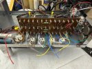
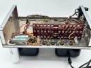
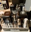
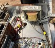
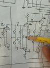
I am rebuilding a pair of MC30s. I am using the instructions from the Mcintosh MacKIT30. In the instructions I can find no mention of a resistor that shows up on the schematic (dated 5.17.60). This is labeled R29, and it is listed as 330kohm. This resistor connects between pins 2 and 7 of the 12BH7 tube. It would be easy enough to strap a 330k resistor across those two pins, but do any of you know if that resistor was routinely left out when assembling these units? What is the purpose of that resistor? Seems like it might reduce some low frequencies or slightly pad the input of each side of the 12bh7?

Thanks in advance for your insight!

-Scott
 

Attachments

  • IMG_1638.jpeg
    IMG_1638.jpeg
    91.2 KB · Views: 36
  • IMG_1639.jpeg
    IMG_1639.jpeg
    72.9 KB · Views: 35
  • IMG_1641.jpeg
    IMG_1641.jpeg
    156.4 KB · Views: 34
  • IMG_1640.jpeg
    IMG_1640.jpeg
    126.1 KB · Views: 36
Register to hide this ad
My Mcintosh MC30 schematic, dated 5-15-1956, shows that resistor, R32, at 330K. That resistor is present on my MC30 pair (1958, I believe). I have a Sams schematic dated 3-14-1960, shows it as R21, 330K. I have another Sams, date unknown, shows that resistor as 220K. Realizing this may have been updated, I think I would stick with Mcintosh schematic over Sams. Paul.
 
My Mcintosh MC30 schematic, dated 5-15-1956, shows that resistor, R32, at 330K. That resistor is present on my MC30 pair (1958, I believe). I have a Sams schematic dated 3-14-1960, shows it as R21, 330K. I have another Sams, date unknown, shows that resistor as 220K. Realizing this may have been updated, I think I would stick with Mcintosh schematic over Sams. Paul.
Thanks for the reply, Paul!

On your Mac is that resistor strapped across pins 2 and 7 of the 12bh7, or is it on the turret board?
 
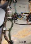
It is on the board. 12BH7, pin 2 has a green wire to the resistor, pin 7 has a green/white wire to the other side. The 220K resistors (R13, R14 on your schematic) to ground are soldered to ground, from the same board terminals. I see the 330K in your picture (goes left to right), but I don't see R13 and 14, unless they are on the back of the board. If pictures would help, I will try to post one for you. I learned to avoid soldering resistors to tube pins, as when the tube is wiggled to remove, it stresses the resistor. Good luck. Paul.
 
R13 and 14 are on the board, and it would be very easy to add the 330kohm resistor there at turret points 9 and 10. I’ll do that. Apparently, they forgot about it when producing the document? Weird that I can’t find anything about this that has been previously posted on the internet. I guess that just tells me that there are very few of this version of MC30 out there.

I used the layout and schematic from this file:


A drawing of the turret board layout to help with assembly is toward the end of the document.

Thanks again for your help!
 
Last edited:
Very interesting assembly document. I had never seen one, and wondered about it. Looks like the resistor in question is on the schematic, but not the board layout. Slightly different layout than my factory assembled units. I guess that would be expected. Anyway, the resistor (330K) is connected on the board across the green and green and white wires from pins 2 and 7 from the 12BH7 socket. I wouldn't see an issue if connected differently, as long as it was correct electrically. Hope to see more as you progress. Paul.
 
I ran across this MacKIT30 for sale on eBay, and you can clearly see the 330kohm resistor on the 12BH7 on the socket. There appears to be some missing pages on the MacKIT30 document that I linked to above, so maybe adding this resistor is described on one of the missing pages? Or perhaps McIntosh corrected this in a later version of the kit instructions? In any case, at least we have a real-world example here where it has been added.
 

Attachments

  • Image.jpeg
    Image.jpeg
    114.4 KB · Views: 17
I suspect thats for some sort of self-balancing arrangement. It should apply some feedback from one grid to the other, so I'm guessing it would improve the AC balance coming into the 12BH7.
 
It should not make any difference in how the amplifier functions or sounds if that 330K (r29 in your MACKIT, R32 in my schematic) resistor is on the resistor board, or the 12BH7 tube socket. It's just a matter of which end of a bare wire it is soldered to. Speaking for myself, I would prefer it on the resistor board, as my factory MC30 pair was wired, only because tube sockets can get fairly crowded, especially dual tubes like the 12BH7. Too many wires in close proximity. Other than that, I don't think it makes a difference. Paul.
 
cshumphrey, Looking at the board picture you posted, it looks like the board you have is slightly different than my 1958 manufacture MC30's. The MACKITS were at the end of the MC30 production, and things probably changed some. Maybe that is why the resistor in question is mounted on the 12BH7 socket, instead of the board. Paul.
 
KIT is the keyword in all of this. Just because it was mounted on the 12BH7 socket by someone who built the KIT it doesn't mean that's the best place for it. I'd put that resistor on the board, not the socket.

Based on the layout of the caps on the board, it seems that this follows the McIntosh,(not the SAMs) MC30 schematic from 3•14•60 attached below.MC30_sch1960version.jpg
 
I ran across this MacKIT30 for sale on eBay, and you can clearly see the 330kohm resistor on the 12BH7 on the socket. There appears to be some missing pages on the MacKIT30 document that I linked to above, so maybe adding this resistor is described on one of the missing pages? Or perhaps McIntosh corrected this in a later version of the kit instructions? In any case, at least we have a real-world example here where it has been added.
Hi CH,

Thanks for your message regarding the MacKIT30 listing. Yes, I built it from the original kit.

The schematic shows resistor R29 — a 330K — between pins 2 and 7 on the 12BH7.

And to clarify: the instructions do document this step. Per the Instruction Manual, p.14, Stage 4: First Chassis Assembly and Wiring, item #30 states:
“Resistor orange-orange-yellow, connect from socket S5 lug 2, to socket S5 lug 7.”

So while it may have seemed undocumented, it’s actually there in the build sequence. The eBay photos simply confirm it was implemented as specified.

Hope that helps — happy to share more if useful.

Best,
John
 
Thanks for the replies, everyone.

x3workshop, the layout is from the schematic dated 05/17/60, which is linked in my post above. I have not compared in detail to what you provided, but at a brief glance I think that they are the same.

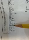
I agree with mounting the 330Kohm resistor on the board. It is easy to add on the board, and that is what I've done. The interesting thing to me is not where the component is located, but the fact that it seems that McIntosh perhaps forgot to include to add that resistor in the original instructions. Look at the test points for pins 2 and 7 in the resistance chart that x3workshop posted. It states that the resistance at those pins should be 220kohms from each pin to ground, but that can't be right. If there is a 330kohm resistor between the two pins it should read less, which I've confirmed.
Hi CH,

Thanks for your message regarding the MacKIT30 listing. Yes, I built it from the original kit.

The schematic shows resistor R29 — a 330K — between pins 2 and 7 on the 12BH7.

And to clarify: the instructions do document this step. Per the Instruction Manual, p.14, Stage 4: First Chassis Assembly and Wiring, item #30 states:
“Resistor orange-orange-yellow, connect from socket S5 lug 2, to socket S5 lug 7.”

So while it may have seemed undocumented, it’s actually there in the build sequence. The eBay photos simply confirm it was implemented as specified.

Hope that helps — happy to share more if useful.

Best,
John
Mystery solved! Thank you, John!
 
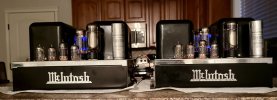
Well, I was finally able to (almost) finish these. I had to deviate slightly from the MacKIT30 schematic because my power transformers are the M-152B models that pre-date the MacKIT30 schematics that I used. The M-152B’s don’t have the tap to easily get the voltage needed for the -45V bias supply. It was easy enough to change a few resistors to match the circuitry of earlier models (using 220k resistors on the output tubes, and ditching the extra set of coupling capacitors the the MacKIT30 uses between 12ax7 and 6L6’s, and changing resistor values for the last 12ax7 to achieve proper bias voltage).

I also A/B’ed the amp with the 150 ohm resistor in the power supply versus using a choke. Both sounded good, but I liked the choke better, so it stays.

7581a power tubes are running at 430V with -45V bias supplly, not too far off spec. The heaters run at 6.5V, so I’ll probably add a few small ohm value resistors to drop the heater voltage a bit to extend tube life.

I’ll spare everyone the audiophile superlative verbiage, but I really do love the sound through my Klipsch Heresy speakers!

I appreciate those who contributed to this thread. Great resource here!
 

Attachments

  • IMG_1677.jpeg
    IMG_1677.jpeg
    64.5 KB · Views: 22
  • IMG_1670.jpeg
    IMG_1670.jpeg
    154.1 KB · Views: 22
  • IMG_1684.jpeg
    IMG_1684.jpeg
    149.4 KB · Views: 20
  • IMG_1685.jpeg
    IMG_1685.jpeg
    91.2 KB · Views: 23
Here's how I dropped my filament voltage. Removed the filament wires coming from the transformer where they landed on the first tube socket, added a terminal strip and some 0.1ohm resistors. Don't remember the final voltage but it was close. You might have to tweak the resistor values a bit. Came out fairly clean.
MC30 filament drop resistors.jpg
 
The 6.3 volt filament specifies within 5%, + or -. I personally would not worry about 6.5 volts, as that is within tolerance. Paul.
 
FWIW, what I always felt was the best way to address the higher filament voltages due to the modern higher mains voltage from the era when these amplifiers were designed, was to simply change the power transformer`s factory default 117 volt tap to the alternate 126 V. tap that is provided to deal with higher mains voltage these amps might be connected to.

Easily done on the 30ties and their higher powered MC-60 brother, and by doing so on mine and every one of these 2 models that have come across my benches since 1975, and doing so have always provided very close to all the schematic`s factory`s voltage values, and the amps seem to appear to operate cooler by doing so, and avoids the insertion of selected low ohm "under the hood" waste heat generating 5 watt or higher sand resistors in the filament circuit feed off the power transformer.

Just a suggestive thought.
 
I think I used the 117V input but with a CL-80 which leaves a few volts of drop when warm. One of these days I'll get my amps on the bench again and do more testing.
 
I think I used the 117V input but with a CL-80 which leaves a few volts of drop when warm. One of these days I'll get my amps on the bench again and do more testing.
I also used a CL-80 thermistor, as well, but in my case for my pair of 30ties & single 60, I converted all three over to SS rectification with chokes installed in the 30s as a substitution for the PS`s dropping150 ohm 10watt sand resistor, so wanted a somewhat softer powerup inrush surge, and with over 15 yrs. later these 3 Mc. tube amps have remained trouble free, so I`m thinking all is still exceeding factory spec. happy within them.
 
Back
Top Bottom