

You are using an out of date browser. It may not display this or other websites correctly.
You should upgrade or use an alternative browser.
You should upgrade or use an alternative browser.
McIntosh - Hints and Kinks
- Thread starter dewickt
- Start date
- Status
- Not open for further replies.
Hot power supply transistor - C27 pre amp
I have a C27 pre amp with circuit board discoloration (overheating?) around power supply transistor Q201, the transistor is hot to the touch. As best I can tell the sound quality is good and the unit is functional. Is this normal or is the unit in need of update/repair?
Dave
I have a C27 pre amp with circuit board discoloration (overheating?) around power supply transistor Q201, the transistor is hot to the touch. As best I can tell the sound quality is good and the unit is functional. Is this normal or is the unit in need of update/repair?
Dave

Bazookatooth
Trouble
I have a C2200 running through an MC2255.
The MC2255 works with other preamps and sounds fine, so i assume the problem is in the C2200.
The sound quality is extremely scratchy and the sound volume is extremely low. At full volume it barely registers on the MC2255's meters. This is the case from all the outputs as well as the headphone jack. I have also tested all the inputs and gotten the same results. In addition, the left channel's meter shows a lower output, and the left speaker (or headphone) is not as loud as the right.
I am new to all of this. Is this something i should have looked at professionally, or are there some things i can try myself (cleaning certain parts, looking for bad connections, or checking the tubes)?
Thanks in advance.
The MC2255 works with other preamps and sounds fine, so i assume the problem is in the C2200.
The sound quality is extremely scratchy and the sound volume is extremely low. At full volume it barely registers on the MC2255's meters. This is the case from all the outputs as well as the headphone jack. I have also tested all the inputs and gotten the same results. In addition, the left channel's meter shows a lower output, and the left speaker (or headphone) is not as loud as the right.
I am new to all of this. Is this something i should have looked at professionally, or are there some things i can try myself (cleaning certain parts, looking for bad connections, or checking the tubes)?
Thanks in advance.

Russellc
Addicted Member
Mc 225 intermittant channel, odd fix...
Well, almost.....while listening the other day, left channel was out. Moving the balance control to that side and turning it up resulted in crackling....
I began to think thru the repair, any oddness, and any areas not addressed.
When I was first done with this amp I noticed one speaker was stronger than the other. I saw one of Terry's posts about the screws on the barrier strip shorting out channel if too long and screwed all the way in. I backed them out and thought I had fixed the problem, but it returned.
Then I noticed that the thump of a screw driver handle on the barrier strip caused the channel to pop back in. Physically moving the barrier strip a wee bit also caused this to happen. Noticing that the mounting screws were loose, I tightened them and this fixed it...or so I thought. After a few weeks of working fine, problem returned. I also noticed that if I grabbed the RCA socket of the interconnect, and wiggle it while hooked to the amp it would pop in and out.
Back on the operating table I got in to inspect the newly installed RCA jack and connection. All is fine. Then attention turned to the little tab that appears to serve as a star ground? Two transformer wires and a few small ground wires all hooked up there. There was a big ball of dry-grey looking solder on it. Fire up the solder remover, and when I touched it to the tab, the two transformer wires fell off! Plus one was only a single strand or two of the multistrand transformer wire. ( I assume they were transformer wires, they had the cloth insulation on them anyway) Removed solder, freshened up the wire ends, securely fastened them and soldered with a nice shiny solder joint.
Apparently, when the barrier strip was nudged, tightened or otherwise fooled with, it moved this tab around, causing the intermittant connection. Same thing with moving the RCA jack.
Now, problem really is solved! Back to
Russellc
Ok, I got it all back together. The two large power supply caps are Sprague
200uf 2 250 volts, screw terminals. The .01 cap associated with them was replaced with a sprague 716 SBE .01 600 volt film cap. The other .01 cap, located on the small power supply board was replaced with the same Sprgue 716 film cap.
The bias cap was replaced with a sprague Atom, 20 uf @ 450 volts. The 33k resistor was replaced with a visay metal film 1/2 watt. The 30K resistor next to it was also replaced with the same 33k resistor, to drop the increased bias voltage caused buy the lessened voltage drop of the 1N4004 diode that replaced the selenium bias rectifier. The .047 bumble bee caps on the board were replaced with Sprague SBE 716 .047 600 volt caps. The .47 caps were replaced with Sprague 730P .47 at 100 volts. The 2 cathode bypass caps were replaced with Sprgue Atom 100 uf 100 volt electrolytic capacitors. The volume controls were replaced with audio taper pots of the same values as the original.
The bumble bees across them were replaced with Sprague SBE 716 .1, 600 volt caps.
Initial fire up via variac, brought the plates up to 390 volts. pin 8. Once stabilized and having stared at the output tubes for red plate the entire time,
I measured the bias voltage at a perfect -21 volts.
Its breaking in now, powering the Indignias. Nice. Thanks to all who threw in the info, especially Terry and Dsloaf, with out who's help this may have been impossible. Hopefully, It'll be ready to go for some time. Most all of the parts used were of industrial strength, like the originals of the time.
Thanks to all for the help,
Russellc
Well, almost.....while listening the other day, left channel was out. Moving the balance control to that side and turning it up resulted in crackling....
I began to think thru the repair, any oddness, and any areas not addressed.
When I was first done with this amp I noticed one speaker was stronger than the other. I saw one of Terry's posts about the screws on the barrier strip shorting out channel if too long and screwed all the way in. I backed them out and thought I had fixed the problem, but it returned.
Then I noticed that the thump of a screw driver handle on the barrier strip caused the channel to pop back in. Physically moving the barrier strip a wee bit also caused this to happen. Noticing that the mounting screws were loose, I tightened them and this fixed it...or so I thought. After a few weeks of working fine, problem returned. I also noticed that if I grabbed the RCA socket of the interconnect, and wiggle it while hooked to the amp it would pop in and out.
Back on the operating table I got in to inspect the newly installed RCA jack and connection. All is fine. Then attention turned to the little tab that appears to serve as a star ground? Two transformer wires and a few small ground wires all hooked up there. There was a big ball of dry-grey looking solder on it. Fire up the solder remover, and when I touched it to the tab, the two transformer wires fell off! Plus one was only a single strand or two of the multistrand transformer wire. ( I assume they were transformer wires, they had the cloth insulation on them anyway) Removed solder, freshened up the wire ends, securely fastened them and soldered with a nice shiny solder joint.
Apparently, when the barrier strip was nudged, tightened or otherwise fooled with, it moved this tab around, causing the intermittant connection. Same thing with moving the RCA jack.
Now, problem really is solved! Back to
Russellc
Last edited:
Hello MAC fans,
I own a couple of McIntosh MCD7000 that I believe is one of the best sounding player made. One of the units starts to become very sensitive and it gets worse after about an hour of operation. One thing I notice is that the "Damaged Disc/Mute" indicator starts off lit when it powers up. It stays lit until it starts playing music. The sound is still excellent but the disk skips too much even with a new disc.
I work a lot on tube stuff but I'm not equipped to work on SS.
Inside the unit, I noticed that when power is applied, the mechanism that holds the lens gets energized but instead of staying close to the inner part where it starts reading discs, it loosely moves in the middle of its linear path as if a voltage is applied momentarily and then goes out.
I was wondering if anyone could share some info on how to tackle this issue.
I hope Terry, the guru, could provide me some hints.
Best regards,
Tony
I own a couple of McIntosh MCD7000 that I believe is one of the best sounding player made. One of the units starts to become very sensitive and it gets worse after about an hour of operation. One thing I notice is that the "Damaged Disc/Mute" indicator starts off lit when it powers up. It stays lit until it starts playing music. The sound is still excellent but the disk skips too much even with a new disc.
I work a lot on tube stuff but I'm not equipped to work on SS.
Inside the unit, I noticed that when power is applied, the mechanism that holds the lens gets energized but instead of staying close to the inner part where it starts reading discs, it loosely moves in the middle of its linear path as if a voltage is applied momentarily and then goes out.
I was wondering if anyone could share some info on how to tackle this issue.
I hope Terry, the guru, could provide me some hints.
Best regards,
Tony

dewickt
Will fix about Anything
The optics will go up and down seeking focus from the laser reflection from a disk, when first turned on it will self check then go to rest waiting for a disk to be inserted. The problem with the optics in the 7000 is as it ages the laser looses power or the optics themselves darken from long use and being hit by the laser, when it can not achieve focus it may or may not be able to read a disk and will tell the processor it is out of range or AGC level is out, thus damaged disk indicator.
Hi Terry,
That was quick. You're a wealth of information.
In my player's case, since it still plays music albeit skipping, I take that as there is still power to the optics. Also, the damaged indicator goes away when playing but correctly flashes while skipping.
In your opinion, is it worth fixing the unit? What do you think is causing the power loss if it's the case?
Thanks for the feedback!
Regards,
Tony
That was quick. You're a wealth of information.
In my player's case, since it still plays music albeit skipping, I take that as there is still power to the optics. Also, the damaged indicator goes away when playing but correctly flashes while skipping.
In your opinion, is it worth fixing the unit? What do you think is causing the power loss if it's the case?
Thanks for the feedback!
Regards,
Tony

Tony - am guessing you will find it impossible to find just the laser, which then needs alignment. You'll likely have to purchase what is called the 'optical block', which includes the laser, premounted, and few additional bits. Problem with older units, which I'm guessing the MCD7000 is, is that these have become scarce. You may find you have to replace the entire transport, which will often include the optical block. Optical blocks run from just under $100 to almost $200. Transports can run 2-4 times that. McIntosh is your best bet for parts (you can e-mail them an inquiry), but also check places like the PartStore on-line. If you are going to open it up to do the work, might as well put in new belts. They are inexpensive and will save having to do so again at a later date if they are stretched. Only you can decide if it is worth the expense. Especially as you can pick up a near perfect MCP861 or MVP871 with far better filters for $1000-1800.

Speaker relay replacement for MC2200 and MC2205 amps
This is just a little piece of information for individuals who tear down and restore their Mac amplifiers.
I was going to remove the speaker relay from my MC2205 and restore it with a DeOxit shot. After seeing how much effort was involved to remove the clear plastic case, I decide to try and get a new relay instead and be done with servicing it for another 30 years.
The original relay is a Tyco/P&B KUP-12D55-48. This is a 3PDT relay with a 48v coil voltage and a clear plastic cover with molded in chassis mounting ears. There are only pins for the normally open contacts. Mouser and Newark only stock a basic inventory of KUP models that is apparently suggested by P&B and there are few choices for 48v versions. The relay I selected is a model KUP-14D15-48. It is a 3PDT relay with a 48v coil but the clear cover does not have the mounting ears. It cost $13.80 plus shipping from Mouser. The relay also has contacts for both the normally open and normally closed positions. Only the normally open contacts are used in the amps. Make sure you mark each of the eight wires so you can put them back in the right positions. The bottom two connectors are for the relay coil. I removed the old relay and very carefully exchanged the plastic covers. I found my best technique for doing this was to take two thin ~ 0.5" wide, 6" steel rulers and carefully wedge them between the plastic cover and relay base so that the rulers are pushed far enough in to go over the two locking tabs on the base. Don't bend the clear cover too far or the little plastic bridge that blocks the locking tabs will crack. Then take a needle nose plier and pull on one of the center relay pins. The cover should pop off. The cases snap back onto the cases very easily. If you are lazy you can probably mount the new relay without using the studs by using strong double sided tape on the chassis. The female push-on pins on the base of the new relay are very slightly narrower than the original so I delicately crimped down the jacks at the ends of the wires to increase the push-in force. The plastic cover can be mounted on the relay base with two possible orientations so make sure you orient the old plastic case on the new relay so the mounting studs are on the same side of the base as the two coil connectors. You don't want to remove the plastic cover a second time. Because the new relay has the extra row of normally closed contacts, put (what was) the top row of three wires onto the second row of pins. Screw the new relay onto the chassis before reconnecting the wires. The new relay works perfectly and I saved a lot of money. I am sure Mcintosh charges much more that $13 for the service part, assuming they still carry it.
John Lovda
This is just a little piece of information for individuals who tear down and restore their Mac amplifiers.
I was going to remove the speaker relay from my MC2205 and restore it with a DeOxit shot. After seeing how much effort was involved to remove the clear plastic case, I decide to try and get a new relay instead and be done with servicing it for another 30 years.
The original relay is a Tyco/P&B KUP-12D55-48. This is a 3PDT relay with a 48v coil voltage and a clear plastic cover with molded in chassis mounting ears. There are only pins for the normally open contacts. Mouser and Newark only stock a basic inventory of KUP models that is apparently suggested by P&B and there are few choices for 48v versions. The relay I selected is a model KUP-14D15-48. It is a 3PDT relay with a 48v coil but the clear cover does not have the mounting ears. It cost $13.80 plus shipping from Mouser. The relay also has contacts for both the normally open and normally closed positions. Only the normally open contacts are used in the amps. Make sure you mark each of the eight wires so you can put them back in the right positions. The bottom two connectors are for the relay coil. I removed the old relay and very carefully exchanged the plastic covers. I found my best technique for doing this was to take two thin ~ 0.5" wide, 6" steel rulers and carefully wedge them between the plastic cover and relay base so that the rulers are pushed far enough in to go over the two locking tabs on the base. Don't bend the clear cover too far or the little plastic bridge that blocks the locking tabs will crack. Then take a needle nose plier and pull on one of the center relay pins. The cover should pop off. The cases snap back onto the cases very easily. If you are lazy you can probably mount the new relay without using the studs by using strong double sided tape on the chassis. The female push-on pins on the base of the new relay are very slightly narrower than the original so I delicately crimped down the jacks at the ends of the wires to increase the push-in force. The plastic cover can be mounted on the relay base with two possible orientations so make sure you orient the old plastic case on the new relay so the mounting studs are on the same side of the base as the two coil connectors. You don't want to remove the plastic cover a second time. Because the new relay has the extra row of normally closed contacts, put (what was) the top row of three wires onto the second row of pins. Screw the new relay onto the chassis before reconnecting the wires. The new relay works perfectly and I saved a lot of money. I am sure Mcintosh charges much more that $13 for the service part, assuming they still carry it.
John Lovda
Last edited:

Gregory
Soundco Kid
This is just a little piece of information for individuals who tear down and restore their Mac amplifiers.
I was going to remove the speaker relay from my MC2205 and restore it with a DeOxit shot. After seeing how much effort was involved to remove the clear plastic case, I decide to try and get a new relay instead and be done with servicing it for another 30 years.
The original relay is a Tyco/P&B KUP-12D55-48. This is a 3PDT relay with a 48v coil voltage and a clear plastic cover with molded in chassis mounting ears. There are only pins for the normally open contacts. Mouser and Newark only stock a basic inventory of KUP models that is apparently suggested by P&B and there are few choices for 48v versions. The relay I selected is a model KUP-14D15-48. It is a 3PDT relay with a 48v coil but the clear cover does not have the mounting ears. It cost $13.80 plus shipping from Mouser. The relay also has contacts for both the normally open and normally closed positions. Only the normally open contacts are used in the amps. Make sure you mark each of the eight wires so you can put them back in the right positions. The bottom two connectors are for the relay coil. I removed the old relay and very carefully exchanged the plastic covers. I found my best technique for doing this was to take two thin ~ 0.5" wide, 6" steel rulers and carefully wedge them between the plastic cover and relay base so that the rulers are pushed far enough in to go over the two locking tabs on the base. Don't bend the clear cover too far or the little plastic bridge that blocks the locking tabs will crack. Then take a needle nose plier and pull on one of the center relay pins. The cover should pop off. The cases snap back onto the cases very easily. If you are lazy you can probably mount the new relay without using the studs by using strong double sided tape on the chassis. The female push-on pins on the base of the new relay are very slightly narrower than the original so I delicately crimped down the jacks at the ends of the wires to increase the push-in force. The plastic cover can be mounted on the relay base with two possible orientations so make sure you orient the old plastic case on the new relay so the mounting studs are on the same side of the base as the two coil connectors. You don't want to remove the plastic cover a second time. Because the new relay has the extra row of normally closed contacts, put (what was) the top row of three wires onto the second row of pins. Screw the new relay onto the chassis before reconnecting the wires. The new relay works perfectly and I saved a lot of money. I am sure McIntosh charges much more that $13 for the service part, assuming they still carry it.
John Lovda
My original 2205 relay was an AMF/Potter & Brumfield 3PST, #KUP 12D56, 36V DC. McIntosh charges 60 bucks for a new one, which I bought. Then found out the quick disconnect terminals are smaller (narrower) that the originals. Ended up buying the correct female QDs and crimping/soldering them on. It came out ok but there were other issues with the amp which caused cut-outs. The original relay was probably working ok. It's too late to re-install it since the terminal lugs are too wide!!
-Gregory
Last edited:
Gregory
Soundco Kid
If your screws on the speaker barrier strips are chewed up and you want to replace them watch out - if the new screws are too long they will short to the chassis.
Hi Terry and all.. I replaced the speaker barrier strip screws in the MC 2505 recently with #6-32 x 5/16" slotted binding head machine screws, 18-8 stainless steel. Best to remove one of the old screws an measure its length. You can order all kinds of NEW screws from McMaster Carr.
-Greg
My original 2205 relay was an AMF/Potter & Brumfield 3PST, #KUP 12D56, 36V DC. McIntosh charges 60 bucks for a new one, which I bough. Then found out the quick disconnect terminals are smaller (narrower) that the originals. Ended up buying the correct female QDs and crimping/soldering them on. It came out ok but there were other issues with the amp which caused cut-outs. The original relay was probably working ok. It's too late to re-install it since the terminal lugs are too wide!!
-Gregory
Yes, the terminals were slightly smaller but crimping down the two rolled edges on the wire connectors seemed to make it quite tight. I'm not going to sit the amp on a shaker table anyway. Interesting that Mcintosh replacements also have the smaller terminals. Looking in the Newark website, it appears these terminals are actually designed to plug into a large plastic socket with two rows of screw terminals. Did you have to swap the clear plastic covers to get the mounting studs?
My original relay was electrically working OK but it was slightly intermittent and I could see a tiny pinpoint burn spot at the center of each contact. Even with DeOxit, I just didn't want to have to open the amplifier again in the future.
All that work was sort of for naught anyway. I jumped for the MC300 a few weeks ago so this one sits and will be up for sale shortly. Between Terry Dewick and I, every cap including the two filter caps and lightbulb were replaced.
Besides the performance, I like having the MC300 because it is about 15 years younger than all the other Mac amps I have had before; MC2125, MC2200 and MC2205. i also didn't have to do anything electrical (ie, circuit repair or upgrade) to it when I got it, just lamps.
John
John
Gregory
Soundco Kid
Did you have to swap the clear plastic covers to get the mounting studs?
My original relay was electrically working OK but it was slightly intermittent and I could see a tiny pinpoint burn spot at the center of each contact. Even with DeOxit, I just didn't want to have to open the amplifier again in the future.
No.. the new plastic cover had provisions to pick up the mounting studs. Understand where you're coming from with the upgrade. Nearly all the 2205 bugs are licked. I'm determined to ultimately get it straightened out. {just between you, me and the wall (board).. this amp has never worked right since I bought it 22 years ago.} The though of upgrading has crossed my mind a few times, however with such a damaged left ear, part of the Mc experience now is making projects out of them, as listening can be difficult with anything above a low power level.
-Gregory

garysrq
Member
2105 resistor help
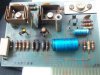
I posted a thread in the mcintosh thread re: q 2105 with static in the left channel - i cleaned the pots, switches etc . Today I removed the circuit board for the left channel and i found some burnt resistors.
My circuit board number is 043-899. The service manual shows circuit board 043-805. I do not have the serial number of the amp, it appears to be wiped off.
There is some difference in the parts on the board - it appears i need R155 ,R131 ,R123, R127 according to my schematic , are these the same for board 043-899
What are the values for those 4 resistors?
I am going to try to post a picture.
Are there other parts that should be replaced while i am replacing the others.
thanks
gary
I posted a thread in the mcintosh thread re: q 2105 with static in the left channel - i cleaned the pots, switches etc . Today I removed the circuit board for the left channel and i found some burnt resistors.
My circuit board number is 043-899. The service manual shows circuit board 043-805. I do not have the serial number of the amp, it appears to be wiped off.
There is some difference in the parts on the board - it appears i need R155 ,R131 ,R123, R127 according to my schematic , are these the same for board 043-899
What are the values for those 4 resistors?
I am going to try to post a picture.
Are there other parts that should be replaced while i am replacing the others.
thanks
gary
Attachments
Gregory
Soundco Kid
There is some difference in the parts on the board - it appears i need R155 ,R131 ,R123, R127 according to my schematic, are these the same for board 043-899. What are the values for those 4 resistors? I am going to try to post a picture. Are there other parts that should be replaced while i am replacing the others?
The blue electrolytic caps?
-Gregory

R155 = 10
R131 = 100
R123 = 150 5%
R127 = 18k
You'll have to check all the parts on that board as those resistors probably didn't burn up on their own. Pay particular attention to the transistors that are connected to them as well as the output transistors.
Look on the other board for R124 (same as R123) If it's brown/red/brown (120) then your sn is below 34M07. If it's brown/green/brown (150) then you're above 34M07.
Murray
R131 = 100
R123 = 150 5%
R127 = 18k
You'll have to check all the parts on that board as those resistors probably didn't burn up on their own. Pay particular attention to the transistors that are connected to them as well as the output transistors.
Look on the other board for R124 (same as R123) If it's brown/red/brown (120) then your sn is below 34M07. If it's brown/green/brown (150) then you're above 34M07.
Murray
- Status
- Not open for further replies.