

You are using an out of date browser. It may not display this or other websites correctly.
You should upgrade or use an alternative browser.
You should upgrade or use an alternative browser.
McIntosh MC-30 Capacitors Choice Please Help
- Thread starter marsfia
- Start date





Source for Illinois Caps?
Hi
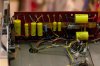
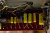
Does anyone know where I can order Illinois Caps (small quantities in the correct sizes)?
Is there another similar (high-value) metallized polypropylene capacitor (axial leads / cylinder type) that can be easily ordered from somewhere?
Also, can someone double check my parts list? (see below)
(I'm working with a technician - rebuilding a pair of MC30 - and I want to make sure I order the correct parts!)
***UPDATED 05/04 as per corrections from JohnWilliams***
Here are the two referenced schematics:
Instruction Manual / Schematic (15329 and Over)
Late Version Schematics
Spreadsheet is here
Thanks!

Hi
Does anyone know where I can order Illinois Caps (small quantities in the correct sizes)?
Is there another similar (high-value) metallized polypropylene capacitor (axial leads / cylinder type) that can be easily ordered from somewhere?
Also, can someone double check my parts list? (see below)
(I'm working with a technician - rebuilding a pair of MC30 - and I want to make sure I order the correct parts!)
***UPDATED 05/04 as per corrections from JohnWilliams***
Here are the two referenced schematics:
Instruction Manual / Schematic (15329 and Over)
Late Version Schematics
Spreadsheet is here
Thanks!
Last edited:
JohnWilliams
New Member
I got my Illinois Caps from Allied Electronics:
http://www.alliedelec.com/
For example:
http://www.alliedelec.com/search/productdetail.aspx?SKU=70112384
http://www.alliedelec.com/
For example:
http://www.alliedelec.com/search/productdetail.aspx?SKU=70112384
JohnWilliams
New Member
You have the wrong Illinois Capacitor part numbers for C10 and C11.
They should be: 224MPW630K
Note that you can always substitute a higher voltage rating for a particular capacitance value. The only downside is the larger physical size of the part.
They should be: 224MPW630K
Note that you can always substitute a higher voltage rating for a particular capacitance value. The only downside is the larger physical size of the part.

classicform
Active Member
With the CE can tie the 30 and 40 together, less ripple, more power, and less distortion.
Sorry to zombie this thread but...
When replacing this can cap I'm seeing conflicting info and just want to get it right in my head.
Tie 30 and 40 together for the original 35 section and use the 80 and 20 for the original 80 and 15 sections?
I've also read tie the 80 and 20 together and use the 40 for the original 35 and the 30 for the original 15.
Terry, are you still recommending tying 30 and 40 together and does this now replace the 35 section?
Thanks...
RShackleford
Active Member
I did pretty much the exact same thing with one of my MC40s, and I CAN compare it to the old one (by putting my preamp in "mono" mode so each MC40 gets the same signal, and rotating the balance knob to one side and the other) and the bass is much improved (presumably due to the 820uF snap-in type voltage doubler caps and 100uF bias supply cap with smaller shunt).Now I did a complete rebuild...every solder joint, resistor and cap was replaced. For the caps I used a mixture of Russian PIO caps and polypropylenes. Jim McShane made the suggestions. Well with one done, I can say it sounds fantastic. Can't compare to the original as both were dead when I got them.
I used Dale/Vishnay metal films for all the caps. Also put in a gold-plated input jack and replaced the NTC thermistor on the line volatge.
I'll do the other one after my buddy with a neglected MC240 (and a better ear than mine) hears the A/B comparison, so he'll tend to his MC240.
For the CE 80/40/30/20, I believe I tied the 80/40/20 together for the main filter cap, and used the 30 for the smaller one (OEM 15uF). I doubt it's critical how you do it. The one I haven't done yet has the older version of the circuit with an add'l filter cap in the PS, and I'll change it to the new circuit (as I describe in "Hints and Kinks Part 2":
http://www.audiokarma.org/forums/showpost.php?p=7348757&postcount=2
Last edited:
classicform
Active Member
Not sure I understand. If it isn't critical then why use different values originally?
Your 240 is a different animal than the mc30 so I'm still not clear on what values to make.
Your 240 is a different animal than the mc30 so I'm still not clear on what values to make.
RShackleford
Active Member
Generally, with power supply filtering, the bigger the value the better - to a limit, because very large values can increase the peak currents on the power transformer windings. This can be mitigated with special types of diodes (soft recovery, etc). This is getting beyond my knowledge level though, so I defer to recognized experts such as Terry Dewick and Jim McShane. As a general rule of thumb, I'd say use values that are at least as large as the original, but not more than double unless you have a deeper understanding (than you or me).Not sure I understand. If it isn't critical then why use different values originally?
True, because MC40/240 have solid-state rectification (i.e. diodes) whereas the MC30 has rectifier tube. But many of the principles are the same.Your 240 is a different animal than the mc30 so I'm still not clear on what values to make.
Anyhow, as people have said, if you're sending to Terry, just trust him. If you're doing the work yourself (or having someone do it who has no particular McIntosh expertise), email Jim McShane and let him sell you whatever parts he recommends (though he likes the snap-in type, which are more compact, cheaper, and readily-available than the FP-type cans, so if you want to keep the original look, go with that CE 80/40/30/20 - which I guess your original question was how to hook it up, so forgive the digression
 .
.
Last edited: