• The move to the new server is done. There are some software and database maintenance updates in process. This has us passing the hat around to help out. We appreciate any donations. Seriously, even a dollar helps. The payment page may be found here - https://www.audiokarma.org/support.html

McIntosh MC225 60Hz Buzz, Vol at Min, No Inputs

The bias line looks clean. I use a piece of wood to manipulate wires (out of habit with high voltage stuff). All soldering is stable. I did resolder related areas, though it made no difference.
My R&S UPV has a high gain when there is zero signal, so I turn on it's internal speaker and can hear hum down in the nanowatt range. Just by redressing the wires, I was able to reduce the hum to inaudibility.
If it's truly a 60Hz hum, it has to generate from a non-rectified part of the circuit. Power cords, power transformer, or heater lines.

:thumbsup:
 
The bias rectifier is half wave, so 60Hz would be the frequency.
True. But, you replaced the caps in the bias supply. Right?

0d2b9ac2-c8aa-4d64-810d-9070c03438c8.jpg
 
Last edited:
True. But, you replaced the caps in the bias supply. Right?
Absolutely! I even added a poly cap across the electrolytic to suppress any RF oscillation that might be happening.
The only thing I hadn't tried was to probe it with a spectrum analyzer to see if something was oscillating in the VHF range, which might explain why grounded wires were acting like antennas.
 
This could be caused by some significant leakage in the power transformer to the chassis. Does the hum go away when the chassis is connected to a good AC line ground?

Dave
 
This could be caused by some significant leakage in the power transformer to the chassis. Does the hum go away when the chassis is connected to a good AC line ground?

Dave
That was my thought early in the game. I measured under 1/2 mV from chassis to earth ground. Grounding chassis had no effect. Just moving the bias wire has ALL the difference!
 
That was my thought early in the game. I measured under 1/2 mV from chassis to earth ground. Grounding chassis had no effect. Just moving the bias wire has ALL the difference!
Yes, whatever works. It's come down to experimenting and knowing that every unit is unique in ground and noise issues.

Welcome to the world of Analog! ;)

:thumbsup:
 
Last edited:
Absolutely! I even added a poly cap across the electrolytic to suppress any RF oscillation that might be happening.
The only thing I hadn't tried was to probe it with a spectrum analyzer to see if something was oscillating in the VHF range, which might explain why grounded wires were acting like antennas.
I also find that older units with original wiring may develop EMF issues — maybe due to the wires becoming brittle. Sometimes, single-stranded copper wire cracks even though the insulation stays intact. And that can cause noise.

It can be a smorgasbord of issues. :oops:
 
I also find that older units with original wiring may develop EMF issues — maybe due to the wires becoming brittle. Sometimes, single-stranded copper wire cracks even though the insulation stays intact. And that can cause noise.

It can be a smorgasbord of issues. :oops:
This wire is multistrand and in good condition-no breaks. It's just oddly sensitive to placement, almost like it's in a saturated VHF RF field.
 
This wire is multistrand and in good condition-no breaks. It's just oddly sensitive to placement, almost like it's in a saturated VHF RF field.
Yes. Prolly the AC heater lines can generate the most EMF. And if they are near any low-voltage signal line, induction can occur.

I remember seeing an animation of EMF fields around wiring. It's quite amazing how many interactions you can't see.

Something like this, but much more complicated.
 
Yeah, I remember reading about how electricity doesn't actually flow INSIDE wires, but in the magnetic field OUTSIDE the wire. That's why those toroidal ferrite beads interrupt RF fields on wires they are attached to.

This is one more thing I made a note to myself about checking carefully the next time I recap an MC225.
 
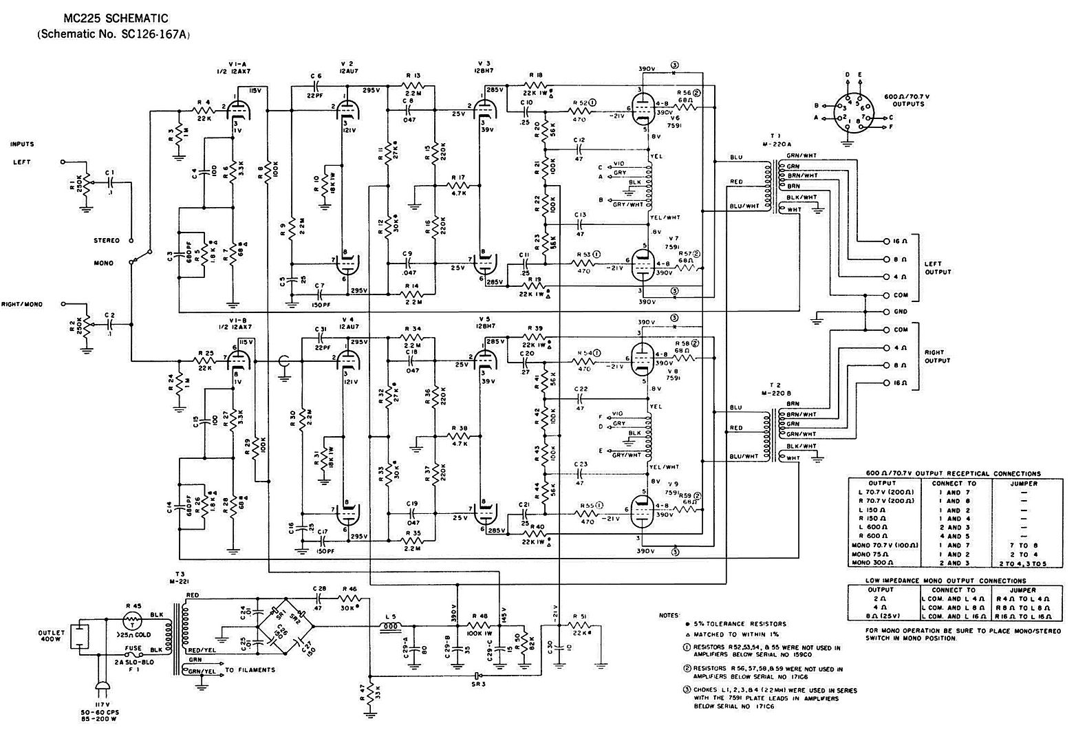
Got a mystery problem here. MC225 amp, all new tubes, s/n A-weighted, left channel 80dB, right channel 72dB.
Audible 60hz buzz with nothing connected to the inputs and volumes at minimum.

Tried the filament circuit modification (ungrounding one side and putting 220Ω balanced resistors across both filament leads to ground. That just made the buzz equal in both channels.

Tried other tubes, same result.

Has all new filter caps. But tried added another cap across the first filter cap in the voltage doubler, but heard no change in level switching the cap in and out of the circuit.

Since this amp spent a lot of time in a garage, I thought maybe transformer leakage. So I checked the chassis to earth ground and did this with the plug reversed too, both times reading under 1/2 mV of AC from chassis to earth.

Oddly, the negative wire, from the anode of the rectifier diode that connects to chassis ground at the cap, acts like an antenna when I touch it and push it toward the chassis. The hum increases in amplitude! So I tried shorting this wire and re soldering it to the cap ground tab, but it still acts like an antenna! See red arrow.

Before I waste too much time chasing this one down, I figured I'd ask the community if they have any ideas as to the cause of this hum.

View attachment 3718730


that bias lead acting as an antenna makes me think you were coupling diode switching trash into the front end through the chassis return, and the wire dress just changed the capacitance enough to show it. i’d try a small rc snubber across the bias diode and also twist the bias feed with its return to keep the loop area tiny, then see if the spectrum shows any hf hash riding the 60 hz. shipping-triggered hum also screams “ground hardware shifted,” so i’d still scrape/retension the exact lug stack at the bias cap and star it to one point. i had a similar “mystery buzz” once after a move and it turned out an rca shell lost bite on the chassis and became a neat little pickup. also, while troubleshooting i kept getting browser popups to https://nodepositbonusesca.com from a sketchy parts pdf site and it about drove me as nuts as the hum.

Key breakthrough: the negative bias line from the rectifier diode acts like an antenna (hum increases when touched or moved). Repositioning it by ½" yielded -10dB. Add a balanced 220Ω to the filament (from ground) and a snubber cap through the diode—hum went to inaudible levels (residual <400nW at the output). A classic for vintage McIntosh: first, relocate the bias line away from the signal lines/transformer, cross it at 90°, and balance the heater—often solves 90% of these problems. Good luck, Basspig, if you haven't solved it yet, let me know when it's finished!
 
Back
Top Bottom