• The move to the new server is done. There are some software and database maintenance updates in process. This has us passing the hat around to help out. We appreciate any donations. Seriously, even a dollar helps. The payment page may be found here - https://www.audiokarma.org/support.html

McIntosh MC2300 Bridge Rectifier

dorrisant

Member
Does anyone know the specs of pn: 070-092? I see a replacement at Audio Classics...

http://www.audioclassics.com/detail?detail=070-092&nav=cat

I'm just wondering if I may be able to find an equivalent by looking at the specs of the original... I could make a replacement with individual diodes if need be, I have quite a variety here at the shop. Is this a taboo idea or have others done it? Sorry to sound like such a noob, but I tried to search for it and found nothing really.

The one I have here had a few output transistors that were way off and a couple that were open, along with a shorted rectifier bridge for half of the output supply. The output transistors are a mix of the originals and three other brands. I would feel more comfortable letting it go with a fresh set.

Also... does anyone have a preferred method for installing the output transistors... I like to use Wakefield and mica insulators but I want to make sure that is the way to go here. A previous repair by an unknown tech (?) left very little compound and three of the output sections had no insulators at all. If there is a rebuild thread out there that would shed some light, I would be glad to read it.

Thanks again!!!
Tony
 
Register to hide this ad
Welcome to AK! Do you have a pic of the original bridge rectifier with any markings on it?

http://www.tubebooks.org/file_downloads/McIntosh/MC2300.pdf

This schematic and parts list indicates the main bridge rectifiers D301 and D301 are the 070-050 part numbers. You could call McIntosh and see if they still stock the original and will sell it to you.

Surely you can easily find 200V-400V 25, 35, and 50A bridges out there in an easy mount case depending on what the original case and mounting were.

Are they mounted on the bottom side wall near the power switch?

AMAC59.jpg
 
Last edited:
So many transistors, so many years ago.........have to admit it has been many years, and a much happier back, that I have worked on the output section of one of these amps.

My schematics and semiconductor data sheets are not here at home, but the Akdatabase schematic says the bridge is 070-050.

Also, if memory serves me right, like it's smaller siblings, the heat sinks are not at ground potential, the + heatsinks are at 40 volts the - are at signal. Therefore only a few transistors are isolated from the heat sink with micas, those on the negative heatsink, shown with a .33 resistor connected to the collector.

On the amp's smaller MC2100 sibling a all to common problem, when these were used in a rough environment, was a heatsink to the perforated cover contact. This was often caused by either something dropped on the unit or the heatsink mounting isolators cracked due to rough handling.

It is late here, and like I said it has been years since I had a MC2300 on the bench, so check my memory via the schematic and with others posted memory.

My back is still happy.
 
Last edited:
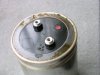
Thanks for the replies!! Here is a picture of the rectifier... and the datasheet from the number printed on it.

I am thinking about just ordering one from Audio Classics... may not find a better deal.

I'm starting to think that some of these output sections might be mixed up. Only four of them should have one transistor isolated and those may have been connected to the wrong rail. If that is the case then it would explain why the breaker was tripping on the unit... and why one of the bridge rectifiers is shorted. It also explains why McIntosh used plastic mounting brackets for these heatsinks. The connections will have to be sorted out during re-installation. Thank you for your advice!! Your help is painting a clear picture now... :)


IMG_20161110_105204204[1].jpg
MC2300 Output Section Txs to Isolate.jpg
 

Attachments

The original 070-05- was subbed by the 070-092 sometime in the late 70s early 80s. It is a 35 amp, 200 volt bridge commercial number MDA3502. That part had a suitable sub added in the late 80s, Mac part number 070-123, which is a MDA3504, 400 volt 35 amp bridge. I am sure Mouser or digikey has a suitable one available.

So many of these were used in commercial applications and fixed on the fly so finding strange repairs is way to common.

A note of caution; since proper repair will demand all the original outputs be replaced with new ONsemi MJ15003G and because the new devices are a tad bit "quicker" than the early 70s semiconductors watch carefully for oscillation.....changing to a driver transistor scheme helps remedy this possible problem on the rare occasion it shows up.

I am trying to picture which transistor and sink has the mica but it has been way too many years......
 
Where are you located? I think there are less expensive options for you.


Digi-Key has a number of suitable parts, from Vishay
$6.19 each 400V 35A GBPC-A terminal
http://www.digikey.com/product-deta...des-division/VS-GBPC3504A/GBPC3504A-ND/357380
VS-GBPC3504A_sml.jpg

or $7.19 400V 35A D-34 terminal
http://www.digikey.com/product-deta...-diodes-division/VS-36MB40A/36MB40A-ND/351975
D-34_PKG_sml.jpg

GBPC terminal 400V 35A $4.82
http://www.digikey.com/product-deta...ion/GBPC3504-E4-51/GBPC3504-E4-51GI-ND/754834
GBPC3504-E4%5E51_sml.jpg

Fairchild 400V 35A $2.91 GBPC terminal
http://www.digikey.com/product-detail/en/fairchild-semiconductor/GBPC3504/GBPC3504-ND/1057387
MFG_GBPC%20DESC_sml.jpg


The Fairchild (now part of ON SEMI) part is inexpensive as is the last Vishay, really all of them, so you could easily replace both bridges quite easily. Be sure to check mounting hole diameter and terminal sizes so they match up with the current connectors, although given the 3504 part numbers, they are likely very close to the replacement MDA3504 unit originally made by Motorola. They all have a heat sink surface which is electrically isolated so be sure to clean off the chassis with alcohol, dry, then spread a thin layer of Wakefield or Thermalloy heat sink grease to the bridge, then screw down to the chassis.
 
Last edited:
The original 070-05- was subbed by the 070-092 sometime in the late 70s early 80s. It is a 35 amp, 200 volt bridge commercial number MDA3502. That part had a suitable sub added in the late 80s, Mac part number 070-123, which is a MDA3504, 400 volt 35 amp bridge. I am sure Mouser or digikey has a suitable one available.

Yup, Audio Classics has the -123 part available, cost is $18 plus shipping! So yes, using the industrial OEM part is much cheaper and avoids the double markups.
http://www.audioclassics.com/detail?detail=070-123&nav=cat
 
Parts came in and are installed.

I would like to check over the driver boards... Does anyone know where I can read service bulletin #039167?
 
Parts came in and are installed.

I would like to check over the driver boards... Does anyone know where I can read service bulletin #039167?

I think you are worried about wrong thing . Reading this service bulletin will not change your 2300 in a 2600 . You better think about the 4 big electrolytic capacitors who schould be very very old now
 

Attachments

  • MC2300-01.JPG
    MC2300-01.JPG
    72.2 KB · Views: 56
  • MC2300-02.JPG
    MC2300-02.JPG
    80.2 KB · Views: 57
  • MC2300-03.JPG
    MC2300-03.JPG
    67.5 KB · Views: 55
  • MC2300-05.JPG
    MC2300-05.JPG
    86.7 KB · Views: 59
If you use the search function you will find a number of posts about this service bulletin. Someone at one time, did post a copy of the instructions that came with the parts kit Mac parts sent.

The last schematic Mac printed back in the 80s listed at least 15 service notes that covered all the updates engineering approved for these amps back then. It does not appear that the available freebee schematics are these complete schematics. I got mine while a warranty service dealer back in the 90s. I am sure you can still get one from Mac parts.

Are you still trying to affect a repair, that is, are you still blowing a fuse? If a bridge failed something very traumatic must have happened in the amp.

Driver transistor failure will often take out the outputs and output failure will often burn parts on the board. I believe someone within the last 6 months bought new boards from Mac parts for this very reason......burnt boards and traces.

Finally as ClinicAudio posted the main filter caps must be suspect, they are very old and often very stressed, but it still amazes me how many still will pass the stress test after all these years. I suspect that soon these will become a must replace part as they continue to age and no longer can be relied on to meet spec. Callbacks suck.
 
All of the electrolytics look to be fine... my ESR meter approves.

I bought a bridge rectifier from a local supply... the one I bought looks like an exact replacement... $7. This passes the bulb test with the finals disconnected.

Cleaned the heatsinks, applied new Wakefield and mica where needed (only four). On Semi MJ15003G from mouser for all of the finals and I replaced all of the resistors while I had it apart that far. I bought 30 TXs and culled them down to 24. Average HFE around 65... Replaced a couple of burnt wire and replaced about 12 or so spade lug connectors.

As far as the driver boards are concerned... There were some very crispy components there and board damage. I have already checked the rest of the components for spec. Had to replace a bunch of resistors. All replacements were 1% metal film. I tested all E-caps for ESR. Pulled all SS devices for testing... I have an Atlas DCA. When I found any bad TXs I replaced them in pairs...

Am I missing anything...

Point is I just wanted to know if there was anything that needed to update on the driver boards... I don't want to do all of the above to have it burn anything up in the future. I was just looking to the best place I knew of to get some help getting this thing purring for a Garcia-fan friend of mine. I have the real service manual here... but I don't see anything about how it should be biased or what to measure where. I am a pretty competent tech and I have some decent equipment but I want to know that this unit is running properly before I let it go.

If the service bulletin is not even relevant, then I don't need it... just need to know it isn't going to self destruct.

I was waiting to put the driver cards in until after I get confirmation that they do not need updated.... Care to take a look?
 

Attachments

  • IMG_20161120_214502749[1].jpg
    IMG_20161120_214502749[1].jpg
    83.7 KB · Views: 75
  • IMG_20161120_214519458[1].jpg
    IMG_20161120_214519458[1].jpg
    89.1 KB · Views: 68
  • IMG_20161120_211627388[1].jpg
    IMG_20161120_211627388[1].jpg
    56.7 KB · Views: 66
I think I referenced in a earlier post, years ago, that service note 15 of the schematic details the last changes to the driver boards when using the last updated driver transistors.

I would never trust a cap tester to test the main filter caps.

I switch my 1kilowatt load box to 4 ohms, dial in my variac to 125 volts, and monitor the rail sag as I cycle thru the frequency spectrum. Between the stress test and also looking at the noise and hum at 60 and 120 hz is the only way I know of to really check the health of the main filter caps.

As for the driver board axials.......they are 50 yeas old, the are known to be failing, the soldering iron is hot, the parts are like $17.00 even with steep shipping charges; I swap in new. Callbacks suck.
 
Last edited:
Hello Dorrisant

What transistor did you used instead 132021 and 132032 and the board on the right in your picture IMG20161120 ? why don't you changed the 2 blue capacitors on your drivers boards ? What transistors did you used in place of the both 132056 ? Are they selected ?

I would never trust a cap tester to test the main filter caps Me too !
 
Holy smokes, you guys are jumpy about those filter caps... I'm not using a cap tester, I use an ESR meter. I don't even have a dedicated "cap tester"... closest thing I have is an LCR meter. Not even using that here... no need.

What is wrong with using an ESR meter to make sure the caps aren't leaky or dead before proceeding? I agree with monitoring the rail while throwing the full spectrum at the amp but you gotta get it up and running first. Those caps are not cheap and it is not my amp to invest in. Besides I have seen countless Fender amps on my bench that have had much older caps and no problems. If they passed the mustard with the ESR meter then I have NEVER had one failure from them, no matter how old they are. Any I have seen that were spilling their guts were tested with the same meter and failed every time. Meaning: a good ESR meter will reveal the health of an e-cap better than anything I've seen yet. Not a capacitance meter... those are only good to find the actual value of the cap in question and will show correct values on caps that would fail an ESR test. Can we all just assume that the electrolytics are fine for now... once up and running I can confirm this.

I will order new and change the e-caps on the driver boards if it will help to ease your minds, fair enough. I know you are looking out for the health of this classic amp. I just don't see spending much time speculating about the main filters.

"What transistor did you used instead 132021 and 132032?"
I didn't change them... only pulled to check and re-install. They are ESR 128 in place of 132-021 and ESR 129 in place of 132-032. I don't know if these are correct or not... this is the kind of info that I'm after. I wonder if these are junk replacements. I know that some brands are junk and want to avoid any related troubles.
 
As a further note... I did change out some of the transistors on the other board. The two 132-056 were changed to NOS 2N5087. Both boards - changed 132-153 to 2N5320 and 132-154 to 2N5322.
 
The driver boards were used in three different Mac amps, Mc2100, Mc2105 and Mc2300. The correct modern commercial part numbers have been posted many times before. Search 132-021 for example.

The main filter caps offer up an expensive trap for any restoration tech, not nessesarily for a repair tech. A repair tech doesn't need to look beyond the warranty time of his repair. After that the client is on their own, it is out of warranty.

A restoration tech needs to look ahead, anticipate future problems and try to get the client's unit ahead of the possible expected future issues. Different mind set, ussually more expensive and much easier to get burned. I think Patrice and I are trying to make clear that this additional expensive development can easily show up once we think the unit is done. Communication with the client is paramount, and this being a open forum the thread followers need to think along with us on these type of things.

These being open forums I believe we try to advance the knowledge of the correct restoration practices and why they most often can not be done on the cheap.

The hobby is sorely lacking in local repair and restoration services. Lots of TV and VCR techs out there but they so often have zero appreciation for high end audio let alone listen to it I believe it is thru forums like this the trade can best be advanced.

There enough of my soapbox. The search function is your friend in these forums.
 
Again... Not my call. If it were mine I would replace nearly everything. The owner was already crying about cost when I told him that all of the finals needed to be replaced. He is aware that I advised from the beginning that he should replace all electrolytics. When/if they do fail he can address it then.

And you still didn't answer my questions...

1- Do the driver boards need an update? I don't know because I cannot find the service bulletin.

2- What is wrong with trusting an ESR meter for electrolytic capacitor health?

Are the caps in this model known to go bad?

I'm not trying to stir up an argument, I just wanted a little bit of info.

Also, why isn't the bulletin posted somewhere as a sticky?
 
Private message Patrice, he might have the bulletins you are looking for. These guys will share their service information privately but not publicly as per the agreement the entered with McIntosh all those years ago.
Nobody is being a snob.

I restored a MC250 a few years back and I didn't update anything, I just replaced the necessary components to get the unit running. You don't have to to the updates. 4 years later the amp is still running as a daily driver......

With regards the to E caps, we all know they have a service life, and at this point in their life, they are well past their service life and so should be replaced as part of preventative maintenance.
The ESR meter will tell you how good the cap is at a certain voltage now, but its not going to tell you how long the cap will last.
I don't even own an ESR meter, I think they are a waste of time.
 
Back
Top Bottom