razpones
Member
Hello everyone, happy holidays
This year I really embraced the electronics repair hobby. I particularly enjoy trying to repair audio equipment, receivers, cassette players and speakers so far. I've had relative success with some receiver and integrated amps that needed basic service of cleaning and replacing bad caps, and because of Covid, and being a student at 50 (welding technology at the local community college), I have very little income right now, I owned a pedicab business (bike taxi) which became obsolete in this times of pandemics. So I figured I had a few pieces of equipment that I could try to fix and sell for tuition money and other expenses. And that is what I have been doing for a few months with relative success as I said.
Now to the point of this post. I would appreciate if anyone could help me with this receiver, I got it from Goodwill and at first it had no sound so I went about cleaning the pots and the switches and was happy to hear it come back to sounding, if not great (compared to others I had before). I believe it might need a recap on the amp board, being from the early eighties and caps are of a not so great looking brand, there are at least 3 different brands, Jollicon, Finecon, and at least one Triumph capacitor. Mostly Jollicon. I only have a fluke multimeter to work with a Fluke 27.
So far, the main problem is the FM radio, I only get full sound out of the left headphone (I have not connected speakers to it yet, but I assume it will be the same). The right headphone you can hear but way way lower, at normal sound level (without hurting your ear), you can barely hear it. It will have a little more volume if you crank it to 9 or 10, but the right side is blasting. I found the radio area to be full of glue, which I believe was already conductive and was part of the problem, as the little I could hear of the radio was terrible sounding, it seems when I was cleaning it, one of the little wire windings got pulled from the board, and for a little while there was no signal, but I put a small wire and reconnected the winding.
The other settings, AUX, Phono, and Cassette all have full sound on both sides as well as AM. So I believe the problem resides on the radio board. I do not have a service manual, so am doing everything blindly. What I have done is test a few of the caps close to the IC i believe to be the one that drive the FM it's marked HA1197. I have tested all the electrolytic caps that are near it . They all took charge and seemed to work, am not super good at testing, but non were open or shorted. My plan is to test all the electrolytic caps on the board, and then if nothing seems off, start testing the ceramic ones, if that goes nowhere, I probably will start testing the transistors. It does seem way to slow and cumbersome though. The other problem is that on the side where the solder is (underneath) there are no markings of what components are or any much info. Everything is marked on the top side, so it is a lot of work finding the caps to extract or what ever I am looking for underneath, and makes it hard to test on the board since I don't really know that it is that am looking at unless I trace it on the top. With out a service manual, I don't really know the values am lookig for either.
The 3 IC on this board are the HA1197, HA1137w, MC1310P
I will post a few pictures of it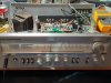
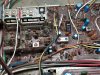
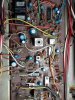
Maybe someone has encountered something similar to this, or maybe it is a know issue? Any help is appreciated. Thanks!
(BTW I wasn't sure if pictures were supposed to be full or thumbnail, so I went for full, I hope it is ok)
This year I really embraced the electronics repair hobby. I particularly enjoy trying to repair audio equipment, receivers, cassette players and speakers so far. I've had relative success with some receiver and integrated amps that needed basic service of cleaning and replacing bad caps, and because of Covid, and being a student at 50 (welding technology at the local community college), I have very little income right now, I owned a pedicab business (bike taxi) which became obsolete in this times of pandemics. So I figured I had a few pieces of equipment that I could try to fix and sell for tuition money and other expenses. And that is what I have been doing for a few months with relative success as I said.
Now to the point of this post. I would appreciate if anyone could help me with this receiver, I got it from Goodwill and at first it had no sound so I went about cleaning the pots and the switches and was happy to hear it come back to sounding, if not great (compared to others I had before). I believe it might need a recap on the amp board, being from the early eighties and caps are of a not so great looking brand, there are at least 3 different brands, Jollicon, Finecon, and at least one Triumph capacitor. Mostly Jollicon. I only have a fluke multimeter to work with a Fluke 27.
So far, the main problem is the FM radio, I only get full sound out of the left headphone (I have not connected speakers to it yet, but I assume it will be the same). The right headphone you can hear but way way lower, at normal sound level (without hurting your ear), you can barely hear it. It will have a little more volume if you crank it to 9 or 10, but the right side is blasting. I found the radio area to be full of glue, which I believe was already conductive and was part of the problem, as the little I could hear of the radio was terrible sounding, it seems when I was cleaning it, one of the little wire windings got pulled from the board, and for a little while there was no signal, but I put a small wire and reconnected the winding.
The other settings, AUX, Phono, and Cassette all have full sound on both sides as well as AM. So I believe the problem resides on the radio board. I do not have a service manual, so am doing everything blindly. What I have done is test a few of the caps close to the IC i believe to be the one that drive the FM it's marked HA1197. I have tested all the electrolytic caps that are near it . They all took charge and seemed to work, am not super good at testing, but non were open or shorted. My plan is to test all the electrolytic caps on the board, and then if nothing seems off, start testing the ceramic ones, if that goes nowhere, I probably will start testing the transistors. It does seem way to slow and cumbersome though. The other problem is that on the side where the solder is (underneath) there are no markings of what components are or any much info. Everything is marked on the top side, so it is a lot of work finding the caps to extract or what ever I am looking for underneath, and makes it hard to test on the board since I don't really know that it is that am looking at unless I trace it on the top. With out a service manual, I don't really know the values am lookig for either.
The 3 IC on this board are the HA1197, HA1137w, MC1310P
I will post a few pictures of it
Maybe someone has encountered something similar to this, or maybe it is a know issue? Any help is appreciated. Thanks!
(BTW I wasn't sure if pictures were supposed to be full or thumbnail, so I went for full, I hope it is ok)
Last edited: