• The move to the new server is done. There are some software and database maintenance updates in process. This has us passing the hat around to help out. We appreciate any donations. Seriously, even a dollar helps. The payment page may be found here - https://www.audiokarma.org/support.html

Microphone Repair Help

Dangerishman

New Member
Hello all!
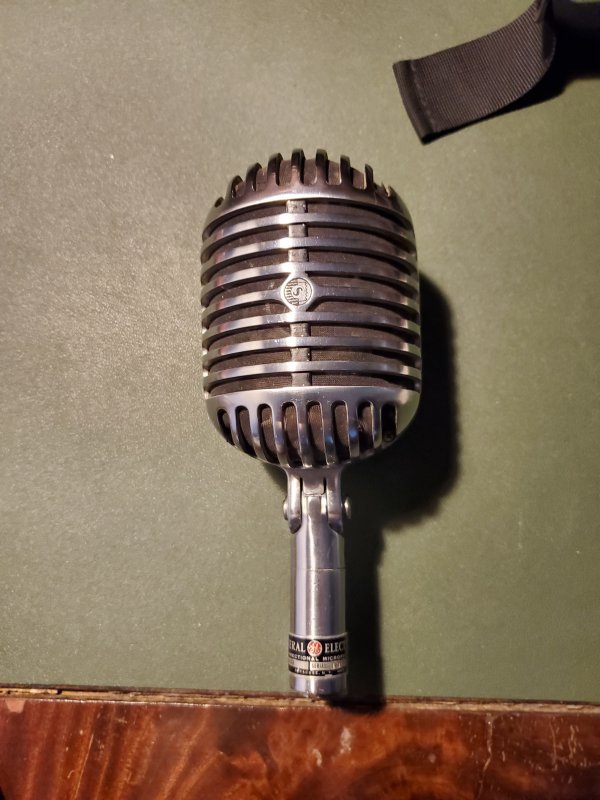
I am working on the blow microphone for a friend. Hooking it up it doesn't produce any sound thru his mixer/amp setup. (See mic below)
index.php
index.php


I am an automation engineer by training but I don't have very much experience with audio equipment. I assume that older microphones like this are dynamic microphones? I opened this one up and found a component that looks like a transformer (though someone told me it is a capacitor, which would make it an odd-looking capacitor).
index.php
index.php


I have also poked around with the old multimeter to see what I can find and I made some notes which you can see below.

index.php
index.php


I have no idea where to start with this mic and I don't really even know what kind of microphone it is. Any help would be super appreciated! Where should I start my troubleshooting? What microphone is this? Am I in over my head?

I also can do more continuity measurements if needed or get more photos, please don't hesitate to ask!

Thanks in advance for y'alls help!

-J
 
Register to hide this ad
Hello. Can you post a pict of the mic capsule, to see what kind of mic is?

Was it working before ?

Do you have an oscilloscope?

Following your diagram seems somebody jumped the transformer, but I can't be sure. Are you sure the transformer is jumped like your drawing (the connections look original but they don't make sense to me, perhaps it's OK and I don't know why this was wired this way, like an "autotransformer")? I'd expect one end (let's call it "ground") interconnected, from the mic to the transformer primary, to the secondary, and to the connector, to make an unbalanced mic. Perhaps you need to cut the wires and make sure about that. The lower resistance winding should be connected to the mic, and the higher resistance winding would be the "secondary", connected to the connector.

But I think you need to disconnect the mic, take notes and picts, and test each part separately. Now you don't know if the wiring is OK, if the transformer is OK or if the capsule is working. Perhaps the capsule is dead, and that's all, no need to bother with the transformer wiring.

People use to save those nice cases and fit a newer mic inside. I've done a couple of those mods, and seen them made by other techs.
 
Hello all!
I am working on the blow microphone for a friend. Hooking it up it doesn't produce any sound thru his mixer/amp setup. (See mic below)
index.php
index.php


I am an automation engineer by training but I don't have very much experience with audio equipment. I assume that older microphones like this are dynamic microphones? I opened this one up and found a component that looks like a transformer (though someone told me it is a capacitor, which would make it an odd-looking capacitor).
index.php
index.php


I have also poked around with the old multimeter to see what I can find and I made some notes which you can see below.

index.php
index.php


I have no idea where to start with this mic and I don't really even know what kind of microphone it is. Any help would be super appreciated! Where should I start my troubleshooting? What microphone is this? Am I in over my head?

I also can do more continuity measurements if needed or get more photos, please don't hesitate to ask!

Thanks in advance for y'alls help!

-J
Google XLR wiring for insight into the connector pin assignments.

The mic capsule assembly looks unmolested, so even though @elnaldo is correct that people do modify these, this one appears stock. And judging from its age I would venture a guess that it's a dynamic microphone. Check out Neumann's site here:

https://www.neumann.com/homestudio/en/what-is-a-dynamic-microphone
 
That’s the legendary Shure 55 Unidyne. It was the first single element cardiod, dynamic microphone. It was made for decades. The transformer might be for impedance matching. Some had switches to select the Z. There is a huge amount of information on this mic across the Internet. Go to Shure.com and search discontinued products. They will probably have something close.

Does yours have a switch? Is there a model number. Can you attach a pic of the connector?
 
Last edited:
That’s the legendary Shure 55 Unidyne. It was the first cardiod, dynamic microphone. It was made for decades. The transformer might be for impedance matching. Some had switches to select the Z. There is a huge amount of information on this mic across the Internet. Go to Shure.com and search discontinued products. They will probably have something close.

Does yours have a switch? Is there a model number. Can you attach a pic of the connector?

It does not have a swtich. The model is number of the YFA-10A.
index.php
 
Also I would ask how much further can I take this apart without damaging it? Also do any of you know what kind electrical connectors they would use?
 
The fragile parts are the transducer and transformer wiring, plus any deteriorating items, like the grille liner material.

To test the mics components, you will need to test the transformer and voice coil for continuity, and testing the connection to the connector.

If there is no switch, then the transformer is a simple impedance matching transformer. The wiring diagram looks like it is bypassed.

The GE badge seems to be a rebadging of the Shure 55 Fat Boy.
 
I have one that looks like that except it says Dukane Corporation on the badge and has a three position screwdriver slot switch that points to H-M-L for impedance (Z) match to an input. It has the same connector too. From your drawing it looks like it has been modified. The pick up coil should go to the transformer with the other end of the transformer connected to pins 2 and 3 with pin 1 to the case. Actually, the pin identification might be wrong but that would be the basic layout... that provides for a balanced output at the two pins from the output of the transformer with the third pin being ground. I just checked it with the microphone... pins 2 and 3 are the balanced output and pin 1 is case, or ground, not signal ground when it is used as a balanced line. The wiring as shown in your drawing makes no sense to me as I see no use for the transformer... like somebody tried to make it an unbalanced output without knowing what they were doing... either that or the windings have some purpose in a unique application which is doubtful. I don't know the actual pickup coil resistance as without disassembly I can only measure the transformer though the switch settings which I am sure connect to different taps on the output of the transformer. Pins 2 and 3 are the balanced output though on mine.

Looking at your pictures the wiring does look original which is puzzling to me... I don't understand why it would be wired like that but who knows. The one I have is from the early sixties and works fine.
 
Last edited:
Go to Shure’s website. Search discontinued products. They have wiring diagrams and diagrams for several models. Remember, this mic was made for over a half a century and it was OEM’ed to others. It’s going to be difficult to find the exact model. However, with sufficient information we can figure it out. Lots of pic is the best way.

I believe this is an OEM by GE of the Shure 55 Fatboy for use with their broadcasting consoles. That would date from the 50s or 60s. The impedance matching transformer would be specific to GE equipment.

It’s a simple circuit on a robust microphone. You are not in over your head if you are careful, have the right equipment, and an ability to solder. If there is a problem with the unit, it will probably be in the mic element. Out of circuit continuity needs to be tested for the element and both coils of the transformer. Then you can use a scope to see the signal at each step of the signal path. If you don’t have a scope, the mic preamp on his mixer amp could be used to listen for the sound. If you don’t have either of these, a phone input on a receiver can be used (although it will sound funny because of the RIAA eq).

You could also disconnect the transformer and run the mic element directly to the mixer input. Today’s electronics are much more forgiving of impedance mismatch than earlier stuff.
 
Last edited:
I would investigate the transformer and the capsule as two separate items. Disconnect the transformer and test the primary and secondary windings for continuity so you know there are no breaks in the windings. If they measure ok the transformer is most likely ok.
My first check on the capsule would be to test for continuity through the coil. I'd guess the coil will measure something like 30 ohms if it's good. If it's open circuit the coil has a break somewhere, which is bad news.
I have known a Shure mic to fail because the coil became detached from the diaphram. That's a very tricky fix which I failed to complete successfully. If it is detached you'll get a good reading when measuring the coil resistance but you won't get sound, other than a clunk when the mic turned upside down as the detached coil flops around.
 
Thanks all! This has been helpful, I'll see what I can do about doing some further disassembly. I agree that the transformer doesn't make a whole lot of sense to me either, and I am fairly sure I traced the wires correctly, but I will double-check and see if I made a mistake. Sadly I do not own a scope (yet but this has made me want to get one). I'll try testing continuity and see what I can find and come back to y'all, maybe we can continue this fun diagnosis.

Also, what does OEM stand for?
 
Let us know your progress. With Rothwell watching this thread you have some serious experience and transducer firepower engaged.
Thanks for the vote of confidence :thumbsup:
However, I did say that I failed to repair the mic where the coil had become detached from the diaphram :rflmao:

One further thought - the transformer is an unnecessary complication initially, so I'd test the capsule without it. You can just connect the capsule to pins 2 and 3 of a standard XLR input on a mixer for testing. Say "one two, one two... two...two, one two". :)
Worry about the transformer after verifying the capsule. Its function isn't really anything to do with impedance matching as such, it's there to raise the mic's output enough to give the mixer plenty to work with. The capsule will work fine without it, just won't be as loud.
 
Thanks for the vote of confidence :thumbsup:
However, I did say that I failed to repair the mic where the coil had become detached from the diaphram :rflmao:

One further thought - the transformer is an unnecessary complication initially, so I'd test the capsule without it. You can just connect the capsule to pins 2 and 3 of a standard XLR input on a mixer for testing. Say "one two, one two... two...two, one two". :)
Worry about the transformer after verifying the capsule. Its function isn't really anything to do with impedance matching as such, it's there to raise the mic's output enough to give the mixer plenty to work with. The capsule will work fine without it, just won't be as loud.
+1, only once I've tried to glue again a coil in a SM57 (those mics suffer a lot, people drop them quite often), and failed to center it. Since then, I just replace the whole element if the diaphragm is broken (the same with headphones). One thing that I did repair successfully is the tiny wires out of the coil going to the connectors. If they are broken outside the diaphragm, they can be soldered again.
 
I visited the Sennheiser factory where I watched them wind voice coils for mics (and headphones). That experience made me give up any pretense about being able to repair a mic element. That is some incredibly fine wire!
 
I visited the Sennheiser factory where I watched them wind voice coils for mics (and headphones). That experience made me give up any pretense about being able to repair a mic element. That is some incredibly fine wire!
Absolutely! I have posted a thread asking for help to solder a tiny wire, it was a headphone VC, the coil had 200 ohm resistance ! (and you need a very thin wire to have 200 ohms in that small coil). A couple of times thinner than a human hair.
 
It's not hard to get 200Ω with such thin wire. The wire is thin to allow more windings and light/sturdy enough to move back and forth 8 thousand times per second or more without breaking.

The transformer is for impedance matching, depending on the amplifier input it needs to connect to. Low impedance wire circuitry will pick up less noise but there could be fidelity losses.

I have an old CB microphone whose dynamic microphone capsule is dead after too many years of vibration - went open circuit. Had to replace with another, I haven't tossed the old capsule yet, but replaced the microphone module with a small speaker that seems to fit (and work...)
 
Hey all! I have done some very careful "unwiring" of the mic to do some continuity tests. One I am going to have to redraw the circuit diagram, I drew it incorrectly (Who uses black and very dark blue as wire colors?!?). All that being said I did a continuity test across the transformer and that seemed fine, but I got no continuity across the capsule at all, and it gave me a measurement of approx 3 Mega Ohms, so that is probably not good. Any thoughts?
 
Back
Top Bottom