• The move to the new server is done. There are some software and database maintenance updates in process. This has us passing the hat around to help out. We appreciate any donations. Seriously, even a dollar helps. The payment page may be found here - https://www.audiokarma.org/support.html

Minimus 7 Loudspeakers - Measurements

Well the mystery SD-52 tweeters arrived today.

Faceplates are bigger but the holes are in all the same places. Possibly a different fabric than the SD-60 tweeters I'm replacing or the same fabric with different doping. The rest of the construction appears identical. I've swapped faceplates on one of them. No audible testing yet.
 
Pete,
Do you think WinIsd gives a reliable estimation of how much power the woofer will handle at given tuning/alignment?

Thanks for the info.

Power handling in speakers is a very complex question. You have a thermal limit due to heating of the voice coil and displacement limits due to the Xmax limit. Both are frequency dependent. Consider a sealed box system where the impedance peaks to 2 - 4 times the rated value, it is actually much more efficient there and draws much less power so the thermal limit is much higher. Same for vented except there is a double peak in the impedance. Most T&S simulators assume a resistive load to simplify the problem and compute the displacement max SPL, then thermal max SPL and displays the lower of the two. You can set the power rating to 10X the actual if you want to just see the displacement limited curve. I believe that WinIsd is a T&S type simulator but I've not used it. Some show the displacement limited curve independently from the thermal. Many companies rate the thermal power limit at 2 to 4 times the actual continuous since speakers are usually used with music having a large peak to average power ratio.
Many drivers will do much more than their rated Xmax. The large Advent has a linear Xmax of about 3mm yet it is easy to see 6-10mm of movement in actual use. This is because the limit is a soft clip and we tolerate the distortion well so with more power there is much more usable displacement. You have to be careful how you interpret the simulator results.

Not sure if I answered your question, do you have any specifics in mind?
 
Last edited:
...

Not sure if I answered your question, do you have any specifics in mind?

Thanks for that answer Pete, I was always curious about how that works in the software and how to interpret it. :thmbsp:

Maybe someone will chime in on how to WinIsd does it in particular. But that's probably a different thread.

I will have specifics in the future, but nothing resembling a plan yet.
 
Well chalk up another successfully modified pair. My black mini7's are all reassembled with the "Sd-52" tweeters seemingly identical to the originals. I haven't done an a/b test with my later model mini7w pair (also modified) but listening to them now they sound fine.

One of these had been so abused that the spring in the positive spring clup had melted through the back of the xover board. Had to disassemble, extract the spring, and backfill the gap with epoxy.

In this pair, all the resistors and the inductor were sourced from Madisound. Had to use two Eagle 20ohm resistors to get to 40 ohms, the 2r is a 2.2r, and the 3r is 25w (iirc) but it comes out a buck cheaper than waiting for P-E to get the inductor back in stock.

I used caps i already had - a couple 2.15uf 1% films and a couple 5uf 5% films selected to be on the low side of 5uf with a capacitance meter (I have a bag of these).

Thanks again!
 
Well chalk up another successfully modified pair. My black mini7's are all reassembled with the "Sd-52" tweeters seemingly identical to the originals. I haven't done an a/b test with my later model mini7w pair (also modified) but listening to them now they sound fine.

One of these had been so abused that the spring in the positive spring clup had melted through the back of the xover board. Had to disassemble, extract the spring, and backfill the gap with epoxy.

In this pair, all the resistors and the inductor were sourced from Madisound. Had to use two Eagle 20ohm resistors to get to 40 ohms, the 2r is a 2.2r, and the 3r is 25w (iirc) but it comes out a buck cheaper than waiting for P-E to get the inductor back in stock.

I used caps i already had - a couple 2.15uf 1% films and a couple 5uf 5% films selected to be on the low side of 5uf with a capacitance meter (I have a bag of these).

Thanks again!

Awesome!
 
Minimus 7 project.

I have been handed a project to install a background music system in 6 rooms of a church owned youth facility. Since it doesn't need to hit concert levels (the facility, named The Rock, is in a residential neighborhood), I chose to use Minimus 7 speakers because they are almost child proof, plus they can be made to sound quite nice. Four pairs are now here, with another few due in a few days. After playing with a pair of them for day or so, it looks like they can be made to be very nice sounding without using the complete crossover in the Zilch PZ 2.1 fix. Simply adding a two resistor LPad to tame the tweeter, and a change of coupling capacitor in the High Pass makes them much more civil. Since there will be seven pairs of them installed in the Rock, there is no sense in spending money that doesn't buy any listenable results. When I am through with all seven pairs, (three done now), I will list the values used.

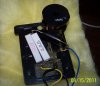
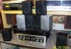
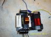
The first pic shows how the LPad is wired in, and also shows the new coupling cap, which is a 3 uF, but I believe could be bigger. The second pic shows the four pairs here now. The top pair is an RCA version, and along with the silver pair were bought from chicks. The pair on the bench playing were the pair bought from Sir.Byrd. They have been sanded and painted. The last pair shows the back, which wasn't painted. It will be against the wall, so who cares how it looks.

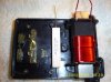
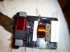
The third and fourth pics show what happens when a magnet comes off a tweeter. This was first noticed when I took the "before" FR. It took some time, but it was finally salvaged. I was afraid the voice coil would be damaged, but it survived to sing again.

 

Attachments

  • LPadInstalled.jpg
    LPadInstalled.jpg
    93.5 KB · Views: 248
  • 4PairsHere.jpg
    4PairsHere.jpg
    114.6 KB · Views: 216
  • OhhOhBadTweet.jpg
    OhhOhBadTweet.jpg
    53 KB · Views: 156
  • BrokeInTwo.jpg
    BrokeInTwo.jpg
    71.1 KB · Views: 243
  • Rock'sMinimus7 007.jpg
    Rock'sMinimus7 007.jpg
    117.9 KB · Views: 242
After playing with a pair of them for day or so, it looks like they can be made to be very nice sounding without using the complete crossover in the Zilch PZ 2.1 fix. Simply adding a two resistor LPad to tame the tweeter, and a change of coupling capacitor in the High Pass makes them much more civil. Since there will be seven pairs of them installed in the Rock, there is no sense in spending money that doesn't buy any listenable results.

Chopping off the wooflet a lot harder before it starts to break up does make it a more pleasing listening experience.

But i agree that in a large installation, with questionable acoustics and where you are just creating ambiance on a budget, it wouldn't make sense to blow a lot of money and time on that part of the filter. Just taking the heat out of them should do enough.
 
Chopping off the wooflet a lot harder before it starts to break up does make it a more pleasing listening experience.

But i agree that in a large installation, with questionable acoustics and where you are just creating ambiance on a budget, it wouldn't make sense to blow a lot of money and time on that part of the filter. Just taking the heat out of them should do enough.

I have modified 8 pairs of Minimus 7's, with a couple more pairs that are still in transit (knowing the kids, we need spares). The HF coupling capacitor seems best between 3 and 5 uF. The last six pairs used a 5 uF film capacitor (3 uF + 2 uF) that was sourced from Erse. The resistor values for the L-Pads are 4 and 10 Ohms. That doesn't sound quite as nice as having the full Zilch PZ 2.1 crossover, but getting about 75 percent of the improvement for roughly 15 percent of the cost makes a lot of sense when it is background music, and will be playing MP-3 music for high school kids.

I managed to get a Nikko Beta 30 preamp to match the Gamma 30 tuner that I had, so they will furnish the FM for when no MP-3s are around, and the power amp is a Crown CE 1000. The wires were all pulled yesterday by three electricians, so now all I have to do is hook it all up. Should be playing in a few days.

If I were keeping a pair of Minimus 7's for my own use, they would certainly have the full PZ 2.1 crossover. Zilch worked at things till they were something he was proud of. That is plenty good enough for me. But for a youth facility background sound system, three fourths is good enough.

The pics show the system working on my bench driving one pair of Minimus 7's, and the eight pair modded so far.
 

Attachments

  • eightpairsMin7's.jpg
    eightpairsMin7's.jpg
    117.8 KB · Views: 138
  • RockSystemElect's01.jpg
    RockSystemElect's01.jpg
    77.9 KB · Views: 105
... getting about 75 percent of the improvement for roughly 15 percent of the cost makes a lot of sense when it is background music, and will be playing MP-3 music for high school kids.

7's serving yet another generation of young listeners. So cool.

Chances are, some of these kids will one day find themselves posting in these forums. Perhaps this very thread -- describing mods to their own Minimus 7's ...
 
Okay, just got funding for the project, can someone with proper software run the numbers for the best cabinet for the woofer? Can be sealed vented or whatever.
Much appreciated!
 
how I did mine

Here is an alternate way leaving the entire plate intact. I chose not to replace the input jacks.
Dremel away parts of the xover mounting plate to leave a flat area to mount the components.
Unwind the .40 mh choke, then cut flush with hacksaw. Remove remaining portion of choke bobin and cut the mounting area flat.
epoxy the 1.0mh choke,3 ohm resistor and .40mh choke to the plate as shown.
Epoxy the 3ohm and 40 ohm resistors together.
when dry epoxy in place leaving room to solder to input terminals.
mount solder lugs. Mine were homemade.
wire according to diagram.
If you are modifying an AV version, you will need to laydown the .40mh choke for the additional room needed for the woofer sheild. Jim:music:
 

Attachments

  • min 7 001.jpg
    min 7 001.jpg
    48.6 KB · Views: 248
  • min 7 003.jpg
    min 7 003.jpg
    46.7 KB · Views: 219
  • min 7 005.jpg
    min 7 005.jpg
    48.3 KB · Views: 251
  • min 7 006.jpg
    min 7 006.jpg
    48.4 KB · Views: 245
  • min 7 007.jpg
    min 7 007.jpg
    46.5 KB · Views: 281
Here are the crossovers I built:
DSC_1110.jpg

DSC_1108.jpg

DSC_1107.jpg
 
They will mount on top of the woofer cabinet, external for ease of change.
The project is to rebuild the minimus sevens into a larger box, roughly 15" tall.
Here is the basic design.
The crossovers will sit behind the tweeters.
Construction is a baffle of roughly 3/4" monkeywood, with all other cabinet walls ~1" baltic birch plywood.
Then, one speaker will house a t-amp with an integrated DAC
These are rough sketches, so don't give me flak, also, the woofer hole is too small, and the tweeter is too far away.
Screenshot2011-09-18at64621PM.png

Screenshot2011-09-18at64627PM.png

Screenshot2011-09-18at64616PM.png
 
Excellent! Hybrid dipole!! External x-over is also an excellent idea. How about letting the woofer run full range?
 
They will mount on top of the woofer cabinet, external for ease of change.
The project is to rebuild the minimus sevens into a larger box, roughly 15" tall.
Here is the basic design.
The crossovers will sit behind the tweeters.
Construction is a baffle of roughly 3/4" monkeywood, with all other cabinet walls ~1" baltic birch plywood.
Then, one speaker will house a t-amp with an integrated DAC

I hope you tested the T-Amp with some modded minimus 7's. I found that my chinese-built TA-2020 based amp had a hard time driving mine, and never did get the combination to sound good together, even after doubling the voltage gain of the amp. Ended up using some pioneer fullrangers for the application i'd wanted the pz2.1 modded minimus 7's in.

Later tripath designs did have more power output than the TA-2020 though.
 
Back
Top Bottom