ubergeeknz
Active Member
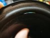
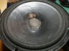
So my faithful Mission 700 Leading Edge speakers have a bit of foam rot going on, time to refoam. While I'm in there I thought why not upgrade/refresh the factory crossovers a bit.
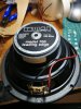
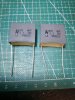
The crossover is very simple ; a 670uH ferrite core inductor in series with the woofer, and a second order filter on the tweeter consisting of a 1 ohm ceramic resistor, 3.3uF and 2.2uF Bipolar in paralel to make 5.5uF, and a 160uH air core across the tweeter. It's all held together with hot glue onto the terminals, which are simple spring-clamp type.
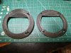
I'm intending to replace the ferrite core inductor with a homemade air core inductor, replace the Bipolar electroytics with polypropylene, and 3d print a new terminal block which will use gold plated brass binding posts. I'll put the crossover on a custom PCB. I've also got some heavy foam material which I can stick to the panels, probably enough for the sides only.
I do want to ask what people think about the following
Should I go all out and add 2 sets of terminals to allow for bi-wire/bi-amp? I don't have such a set up presently but I'm interested to see what people think.
Should I try to brace the box any? These are pretty small and the chipboard isn't too bad resonance wise but I wonder if a simple brace on the sides will improve matters slightly?
Where's the best place/way to install the crossover board?
Any other suggestions while I have these apart?
Thanks in advance! And yes, I'll post some photos of progress/before and after etc.
The crossover is very simple ; a 670uH ferrite core inductor in series with the woofer, and a second order filter on the tweeter consisting of a 1 ohm ceramic resistor, 3.3uF and 2.2uF Bipolar in paralel to make 5.5uF, and a 160uH air core across the tweeter. It's all held together with hot glue onto the terminals, which are simple spring-clamp type.
I'm intending to replace the ferrite core inductor with a homemade air core inductor, replace the Bipolar electroytics with polypropylene, and 3d print a new terminal block which will use gold plated brass binding posts. I'll put the crossover on a custom PCB. I've also got some heavy foam material which I can stick to the panels, probably enough for the sides only.
I do want to ask what people think about the following
Should I go all out and add 2 sets of terminals to allow for bi-wire/bi-amp? I don't have such a set up presently but I'm interested to see what people think.
Should I try to brace the box any? These are pretty small and the chipboard isn't too bad resonance wise but I wonder if a simple brace on the sides will improve matters slightly?
Where's the best place/way to install the crossover board?
Any other suggestions while I have these apart?
Thanks in advance! And yes, I'll post some photos of progress/before and after etc.