

You are using an out of date browser. It may not display this or other websites correctly.
You should upgrade or use an alternative browser.
You should upgrade or use an alternative browser.
Mission 770s hack job on crossover
- Thread starter Audi0
- Start date


StimpyWan
Addicted Member
One of the sets of eBay crossovers (not mine), was selling really cheap. It might make for a good platform, to rebuild a matched set? I'd reuse the inductors, and buy new caps. Falcon would be good for that, as their caps are supposed to be voiced to match classic British speakers. They're the go to shop for KEF recaps.
StimpyWan
Addicted Member
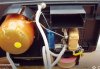
Both crossovers match. It's the red circles are what I suspect was done to both speakers. I was going to pull the parts which that I suspected were added. I don't see how it would damage it.
If the crossovers match in both speakers, then why disassemble them? Do the speakers currently sound bad as is? If not, I really don't see the reason to undo the mods?

Audi0
Super Member
If the crossovers match in both speakers, then why disassemble them? Do the speakers currently sound bad as is? If not, I really don't see the reason to undo the mods?
Was not impressed by them in there current state.
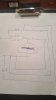
This is my closest guess to the factory crossover. It' the high pass? That I'm unsure of.
Attachments
Mission got back to me as I contacted them yesterday. They seem to have the crossover schematic. Let' see if they send it.
Good deal. If they do you should post it to AKDB and maybe HFE so the next person who has a question on these can get info.

Audi0
Super Member
I may have some 770s at my shop. I will try to look tomorrow.
Tony
Even if it's a revised crossover it gives a solid basis to a build a new factory one.
Last edited:
StimpyWan
Addicted Member
It seems the 770S speakers were designed as a more 'affordable', budget version of the 770. One of the differences mentioned between the crossovers, were the lack of resistors, in the 770S. The resistors were there to balance the driver output to each other. To balance the tweeters. So, I have to wonder if 770S owners modded their crossovers, in an attempt to mimic the sound of the 770?
Also, all of this Mission talk makes me miss my 780 Argonauts. They were stolen during a move!
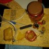
Not mine, but mine looked like these.

Also, all of this Mission talk makes me miss my 780 Argonauts. They were stolen during a move!
Not mine, but mine looked like these.
Last edited:
Audi0
Super Member
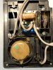
Here's a picture. If you need me to I can trace the crossover this weekend.
Tony
Can you trace it out? I can start rearranging to what you have shown with the avaible
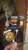
components. I just need the value of the 3 resistors. Look what else I found thx to the pictures this contact point was cut. It attaches to the other side of the inductor.
U can kinda see what was done comparing the 2 crossovers. Still hoping mission sends there scan of the crossover.
Last edited:
Audi0
Super Member
I made this quick schematic from those 2 pics. The only thing I need info on is the bypass under the inductor. How is it wired in circuit? Whats The value of the resistor? Do you think the parallel resistors are supposed to be wired to the bypass and not before the inductor?
Look at the changes. The big red circle is the area im unsure of.
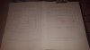
Look at the changes. The big red circle is the area im unsure of.
Last edited:

