• The move to the new server is done. There are some software and database maintenance updates in process. This has us passing the hat around to help out. We appreciate any donations. Seriously, even a dollar helps. The payment page may be found here - https://www.audiokarma.org/support.html

Mitsubishi DA-A7DC help needed

Kahoona

Super Member
Hi
I am hoping that some kind soul can offer some help. I have a DA-A7DC that I picked up recently. I wanted to set the bias and DC offset.I found this thread and I have set DC on many amps.

http://www.audiokarma.org/forums/index.php?threads/mitsubishi-da-a7dc-bias-and-dc-questions.441384/

I could not get the offset to 0 so I decided to replace the trimmers, which were behaving unevenly and were mostly cheap junk. Problem is there is not much information on what they are!


VR-201 on the schematic is labeled 104w. 104 means 100k ohms (?) and this is the only 100k ohm with solder lugs in Mouser. I can't find out what the w means. It measures 54k ohms but that is probably due to decreptitude.

http://www.mouser.com/ProductDetail/Murata/PVZ2A104C04R00/?qs=w0dpS%2beAnTmK3IO1Kbwvjw==

VR-203 , labeled 202y must be 2K 5% (meaning of y unknown) and it measures 1.5k ohms. Again the measurement is probably off. There are 2 available. Will they work do you think?

http://www.mouser.com/Search/Produc...virtualkey64800000virtualkey81-PVZ2A222C04R00

The third one is VR-202 and I have no idea what replaces it. None of the numbers match up or translate. It seems to be made of better stuff but it still has a bad spot when tested while being turned. It measures 0.60k ohms Mouser has nothing stocked in 680 or close. I am hoping that I can make the old one work. I think it is the fine adjustment.

Do you think I have it right? I did a bit if research to get here but will these trimmers be OK? I have a few other things I want to replace but that is all straightforward I hope. The other side sets OK.
 
Register to hide this ad
are you measuring between the external pins?

The blue one is clearly marked 680 ohm. A 1K will work of course. You'll have less accuracy when adjusting, but for sure you can get any value between 680 and zero with a 1K pot. Or, something like this 600 ohm should work.
http://www.mouser.com/ProductDetail/Bourns/3266X-1-601/?qs=sGAEpiMZZMvygUB3GLcD7sSg8po3Zpo3C7ykpNfHs2M=

The other 2: I agree with you about the values , 104 should be 100K. Confirm with the schematic, but if it measures 54K now, a 100K won't hurt. Same with the 2K.

The links you posted are SMD devices, they won't fit, you need a "through hole", this kind or similar: http://www.mouser.com/ProductDetail/Bourns/3362P-1-104LF/?qs=sGAEpiMZZMvygUB3GLcD7l39JMs///LOs09gVZSzi2c=

Check the sizes and wattage rating before ordering
 
Last edited:
Hi
Thanks for answering. Sorry I didn't see the reply right away. I guess I did not have notifications set properly.
I cannot find a schematic for this which is why I am nervous. I am measuring the 2 pins closest together (on the left in photo) for overall resistance and one of those pins and the far single pin while turning the slide to check for operation.

I see where I made the mistake when choosing! I do know the difference too. Here are three that should work. Do they look alright to you? I, myself, love the multi turn Bournes with the side screw but in this case I am supposed to be setting the bias with the board in place and I'll only be doing them once anyway so I opted for through hole.
Thanks
http://www.mouser.com/Search/Produc...02KT20virtualkey61330000virtualkey72-T70YU-1K

http://www.mouser.com/Search/Produc...KT20virtualkey61330000virtualkey72-T70YU-100K

http://www.mouser.com/Search/Produc...02KT20virtualkey61330000virtualkey72-T70YU-5K
 
I am sorry but I need to ask another stupid question. I need to replace several resistors. Here is a picture of the ones from the right channel which look fine.


I need to replace the ones on the left. I have the resistance figured out and they appear to be film resistors. I can't figure out what voltage to get though. How do you do that? I did some research but can't seem to figure it out. Any suggestions?
 
The trimpots, seems OK, but check the position of the adjustment screw, there are usually 2 types,adjustable from top, or from one side. Also, a multiturn could help in the 680ohm place, where you are replacing with 1K. But don't over-think about it, any of this will do the job, better than your bad pots.

The resistors, look like carbon resistors, 1/2 Watt (the smaller is 1/4 Watt, and the 1Watt are larger than those). So, you can use carbon film or metal film, 1/2 watt for the larger ones, 1/4 watt for the tiny one. 1/4 Watt metal film are very small nowadays, and the 1/2 Watt will be as small as your 1/4 Watt. It's not a mistake if you receive small metal film resistors for the 1/2 watt.
 
OK. Thanks. I am pretty sure I found the right stuff now. A couple of the resistors were not available in the exact decimal point of resistance but I found them within o.1 and since tolerance is 5% I assumed that was OK. I got my Mouser order together and then figured I'd better do the bias and DC on the Mitsu 10DC also in case I have to order trimpots for it also. I have the service manual for that one, although it is confusing on those things. I'll let you know how I make out with the 7DC when the parts come in. If I run into trouble with the 10DC I'll search on that before posting it.
I really appreciate the aid, specially from someone with an Infinity in their avatar. I love the older infinities! I have a pair of the Haffler Infinitesimals in my RV system. My wife thought that we had three different speakers on each side because of the wonderful soundstage that they have.
 
You are welcome, post back the results when the parts are there.

Also, keep in mind if a resistor blew, something did that. Check what component in the circuit was the cause.
 
You are welcome, post back the results when the parts are there.

Also, keep in mind if a resistor blew, something did that. Check what component in the circuit was the cause.
Thanks. I will test them to see if they are blown. My main reason, believe it or not, is cosmetic. They have gotten kind of powdery looking because of the damp shelf the unit sat on in my friends PA basement. I am planning on seeing how well I can set the Bias and the Offset, then give it a lix ten. Nothing else looks blown. If the voltages fluctuate then I will need to start testing. Probably diodes and smaller transistors first. Possibly recap the power supply. I am concerned that those smaller transistors aren't available though and I doubt that there are updated parts list like Markthefixer makes for the Pioneer things. I have learned things on this project and will learn more so this is part of the learning process. For this we can be grateful. Today, between turkey prep and dinner I will try to find out why the bias and offset instructions in the 10DC don't make sense. Probably a translation problem.
Thank you for your help. No thanksgiving in Buenos Ares so I can't wish you one!


Here is the status: I boogered it up. (Southern New York State hillbilly dialect). Pronounced as if it had three long o's. No I am not but I worked there for a while. I did have some fit adjustments to make. With the Vishnu trimmers I could not find any way to tell what the leg configuration was. There was a chart in the materials data sheet but it did not include the ones I got. I figured there would be 3 legs in a triangle eigh?. No. Still I got them oriented and nicely installed with a single discrete jumper each. I replaced the resistors. Please remember that my interest was partly cosmetic since those on one side looked moldy so I did both. All went well. I fired it up and went to set the bias. The new trims were a thousand times netter and after a few minutes of fiddling the voltage was spot on and remained spot on for an hour without wavering. Sweet! I told my wife that I thought I might have gotten it right. Bad Ju-ju there. I went for the DC offset. The MV's simply rose higher and higher with only minimal response to the trimmers. I cut it off at 500 and did some checking. I measured the old resistors which sat in the bottom of a cup like a bunch of old teeth. They were all good and using them I found that I have definitely gotten a couple of the new ones wrong. It was that 3rd color bar. That and the faded colors. I have learned now. I have been spoiled by parts lists and Service Manuals and forgotten my colors and multipliers. More are ordered but since both sides were identically wonky I am sure it will work fine once I get the right ones in. I'll report back!.
 
Hi.
Happy holidays to all. Hope that you are doing well. My wife has been hoisting my amps up onto my work area for me and my back is feeling much better.

Here is the state of the A7DC;
I did get the right resistors and swapped out the bad ones.
I left it to simmer on the DBT for eight hours just to make sure that everything was fully dry as was suggested.
I set the Bias on both sides and it was spot on and stable.
The DC Offset is a problem. I can set it to 0 but it drifts up and down several mv's. If I leave it alone for ten minutes it will rise to 190mv or so. I can reset it but it will happen again.
I am wondering if I don't have a problem in the power supply. The problem is the same on both sides. The strange thing is that I have the same problem with a A10DC. Is it something I am doing??? I have the speaker selector to A. The Tripplet 9045 to DC Volts. The probes in the speaker wire connections. Does anyone have any suggestions? The bias can be set but the offset is unstable.
I cannot find a manual for this one.
 
Could it be "thermal runaway" ?? Did you replace some transistors? Usually, circuits tend to stabilize , with some components conducting more or less current , balancing things until stabilize.

It seems it shares the manual with other amps, A10DC perhaps?

Can you monitor the + and - rails to see if they follow this "unbalance"? If the problem is at the PS, you should see some of the 2 voltages drifting, causing that "offset"... If the + and - V rails stay stable, it's not the PS. But a leaky capacitor on one rail could drift some voltage and unbalance the DC offset...

I don't see a problem with your measurement procedure. Do this with volume at minimum, or even shorting the input, to be sure you are not amplifying a signal. Also, be sure the relays are engaged, so you are really measuring the amplifier circuit connected to the speaker terminals. If not, find the test point at the PCB and measure directly there.

Some units never stabilize, but I've seen DC moving up and down just some mV...
 
Last edited:
Could it be "thermal runaway" ?? Did you replace some transistors? Usually, circuits tend to stabilize , with some components conducting more or less current , balancing things until stabilize.

It seems it shares the manual with other amps, A10DC perhaps?

Can you monitor the + and - rails to see if they follow this "unbalance"? If the problem is at the PS, you should see some of the 2 voltages drifting, causing that "offset"... If the + and - V rails stay stable, it's not the PS. But a leaky capacitor on one rail could drift some voltage and unbalance the DC offset...

I don't see a problem with your measurement procedure. Do this with volume at minimum, or even shorting the input, to be sure you are not amplifying a signal. Also, be sure the relays are engaged, so you are really measuring the amplifier circuit connected to the speaker terminals. If not, find the test point at the PCB and measure directly there.

Some units never stabilize, but I've seen DC moving up and down just some mV...
Thanks for all of the info. I will check on those things one item at a time. I may have at ask a question or two if I cannot research the terms.
I have not replaced any transistors but someone may have at some point.
Closest manual I can get is the A10 (not A10DC). It does have some similarities.
I'll start with input gain off then and then try shorting the inputs. See what happens. Then I'll read up on the "rails". I am familiar with the concept but not sure where they are. I'll report back. Thanks.
 
You can measure V+ at the positive filter capacitor, and V- at the negative end of the other capacitor...

It would be good to compare voltages agains a schematic. Try to identify similar points in your unit, speacially around the DC offset trimpots.
 
You can measure V+ at the positive filter capacitor, and V- at the negative end of the other capacitor...

It would be good to compare voltages against a schematic. Try to identify similar points in your unit, specially around the DC offset trimpots.

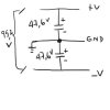
Eureka! One rail is 95.2v and the other is 47.6v. That's a huge difference! I assume that I should test those big filter caps now and I will see if I can identify any similarities in any schematics available. I have a schematic that Terry S maybe that will help me. Would a bad cap cause it or is it likely to be in some sort of controlling circuit?

http://www.audiokarma.org/forums/index.php?threads/mitsubishi-da-a7dc-bias-and-dc-questions.441384/

otherwise one for a DA_A10 is the closest.It is not the DA-A10DC. I'll report back.
 
It can´t be that high, something is wrong, be sure you are not measuring from the "V-" to the "V+".

Measure from ground (chassis, or the point where both larger capacitors are interconnected, it must be a positive and negative ends together). This way, you should have +47V to one capacitor lead, and -47V to the other capacitor lead.

If you have +95V from ground , something is miss.wired !

I think you are measuring referenced to the "-" rail.
Untitled-1.jpg
 
Last edited:
It can´t be that high, something is wrong, be sure you are not measuring from the "V-" to the "V+".

Measure from ground (chassis, or the point where both larger capacitors are interconnected, it must be a positive and negative ends together). This way, you should have +47V to one capacitor lead, and -47V to the other capacitor lead.

If you have +95V from ground , something is miss.wired !

I think you are measuring referenced to the "-" rail.
View attachment 664412
I get it. Sorry I misunderstood. Yes. Both are steady at 46.9 so that is good. I realised I can't measure the big caps with my Triplett anyway since they are out its range.
 
If you look at this schematic made by Terry S. There are two points reading -30 and +30 they are on either side at the bottom. Best I can tell they are corresponding to spots on the board for the right chan marked 7 and 11. 7 measures 45.8v and 11 measures - 48.5v.

The corresponding spots on the left are 27 and 31. 27 measures 45.7. and 31 measures 48.6
Are these off enough to suggest anything? They are pretty steady.
 

Attachments

Last edited:
Hi
Here is the board. I notice that photos may be smaller in the new format. I can send a ling to a real big one if you want. It is upside down. Sorry
I see that I have numbered attachment spots at the bottom (top really) of the board, They are in 2 sets. I measured them all

Right side.
27/orange=+46v
26/yellow=+85v
29/gray=-580mv
31/Blue=-40v
28/Green=+64v

Left side
8/Green=+1.5v
10/Brown=+1.5v
11/Blue=-49v
9/Gray=+9v
6/Yellow=+2.2v
7/orange=+46v

SO something is wrong on the left chan. I think that I had better double check my measurements tomorrow. I am tired.
Tomorrow I may be able to see what I can figure out by following the leads.

Please have an enjoyable holiday Elnado. If you celebrate Christmas it is a hot weather holiday for you but here in South Florida it is also a warm holiday.
Thanks.
Right side up now


Attachments

  • DSC02002.JPG
    DSC02002.JPG
    95 KB · Views: 5
OK; HAve also a nice christmas there!

Regarding this, we 1st need reliable numbers. To have that, we need to identify the points on your PCB.

Please, try to identify the pins on the schematic. Check the components connected to them.

Let's identify first: Ground, Output (R131-132 junction), V+ (Q111 Collector) and V- (Q112 collector), Then, identify the 2 zener diodes D102 and D101. Those are reference voltages, they need to be steady and I guess, symmetric.

Then, measure always with black probe to Ground, red probe to the test point, so we have reliable polarity. It's important at this stage.

Also, find VR101 and VR102, those are the DC offset adjustments, I guess Input offset and output offset. I'd set the trimpots at the middle position and start from there. Check you got the right values. If in doubt, fit the original parts for the tests.

I don't trust the soldering at R129, VR101 and 102 in your picture. Neither at VR203. Try to clean that up, check with a mag. glass and remove any solder that could cause a bridge. Check all the board with a mag.glass, or take a high resolution pict (6 Mpix or more) and do a zoom on your computer. That's better than a mag.glass.
 
Back
Top Bottom