• The move to the new server is done. There are some software and database maintenance updates in process. This has us passing the hat around to help out. We appreciate any donations. Seriously, even a dollar helps. The payment page may be found here - https://www.audiokarma.org/support.html

Mitsubishi DA-U310 Restoration

Eastham

More Class-A than ever!
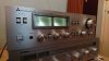
So I saw this amp on fleaBay and decided after looking up it's specs and taking a gander at the internals of this guy online that I'd make an offer. We settled on £65 and it's now on it's way to me. I think it was the VU meters that caught my eye, who doesn't love a nice pair of VU meters! :naughty:

I've never heard much opinion on Mitsubishi amp's and was wondering what the general opinion is on these, on paper the specs suggest it should stack up pretty nicely. 55WPC, 0.03% THD. But the proof is in the puddin' so to say. Anyone heard Mitsubishi gear or owned any of their amps? I found a picture of the internals and they seem to back up what's on the paper, 10,000µF filter caps, decent sized trafo, and some adequate looking heat sinking.

I also noticed that the amp stage has four output transistors per channel, forgive me if this is a stupid question but why? I've noticed that some more serious amps use several output trannies per channel and it's always intrigued me. Either way it's pretty cool, must be a lotta pushing and pulling in that amp stage. ;)

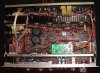
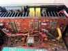
Not my pics but here's some I found of the internals on the interwebs
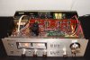
mitsubishi-1_355709.jpg mitsubishi-1a_355707.jpg ruhestrom_356734.jpg
 
Register to hide this ad
Mitsubishi gear is rare and info even more rare.

I like and liked all the stuff I ran across.

Multiple output transistors are used to get more power from devices that can't handle it alone.
Those look to be TO-220 transistors and getting 55wpc from just one pair is not possible. They just are not strong enough by them selves.
 
Mitsubishi gear is rare and info even more rare.

I like and liked all the stuff I ran across.

Multiple output transistors are used to get more power from devices that can't handle it alone.
Those look to be TO-220 transistors and getting 55wpc from just one pair is not possible. They just are not strong enough by them selves.

So that's why, I had a feeling it was something along those lines but I wasn't quite sure. The output transistors are those weird ones that look like TO-220's but withe the wings on the sides with screw holes in them.

A9aTH3G.png


Edit:

XM20 I think.
 
Last edited:
So that's why, I had a feeling it was something along those lines but I wasn't quite sure. The output transistors are those weird ones that look like TO-220's but withe the wings on the sides with screw holes in them.

A9aTH3G.png


Edit:

XM20 I think.

AH! We call those "bat wings". I forget their designation. Totally obsolete. We make TO220 fit as replacements.

I've been hoarding the good ones I find for easier fixing.
 
Bat wings? They must have been made by Wayne enterprise... *I'm Batman*

I can see how you'd probably be able to make a TO220 fit, slap it on the heatsink with some paste and put a metal band with two holes drilled into it across it. Though because I love making life hard for myself I'd try drilling and tapping a hole in the heatsink. Hoarding parts is the best we can do now, I've got a small collection of biasing diodes and obsolete trannies. Those batwing trannies mustn't have lasted long, I guess that the TO220 transistors where just as good.

The amps should be here today and hopefully it's unmolested, the seller said it works so that a positive.
 
Well, it got here not half an hour after I posted that.

DSC_0817[1].JPG

YUK! This is by far one of the dirtiest amps I've ever bought.

DSC_0820[1].JPG

After a good hour of cleaning i've gotten it to an acceptable point, just adjusting the Bias. Left channel was way outa wack 63mV and the right was at 38mV I adjusted both for 30mV ish. DC offset gives this amp a clean bill of health, 3.2 mV on the left and 1.8mV on the right. Still probably going to perform a full recap and find some noisy resistors. The previous owner replaced the lamps with LED's very badly too, just a cap and a resistor, I would have liked to have seen some rectification. I'll probably just get the correct bulbs, same type as in Cassette decks long thin lamp with wires out either end. This thing sure does sound great, it's very clean and clear with nice hard bass. I'll hook my 'scope up along with my dummy load later and see how much power this thing can really push out. The only problem I've ran into so far is my damn sensitive speakers! :mad: To get the VU meters bouncin' I have to wear ear muffs.. But all in all this amp is pretty nice, a definite sleeper if you ask me.

DSC_0821[1].JPG
 
RE: bat wing replacement. A trick is to use the old transistor as the clamp and get longer screws.

Unless you really need to know full power, I would hesitate running it into dummy loads at full power to see. With the adjustments reading ok, it may be fine but a full load on old parts makes me nervous.

Just saying.
 
I decided to take a closer look at how this guy hooked up the LED's in the VU meters, no only where they crazy dim my camera made them look brighter than they where they flickered badly.

DSC_0825.JPG

Who ever did doesn't look like they knew what they where doing, a 1K resistor! Into a 1N2007 (if I'm reading it right) and a 22µF cap for filtering... I guess he thought adding a high value resistor would stop the flicker.

My attempt. A admittedly overkill full bridged rectifier I found in my parts bin with a 100µF Panasonic FC low esr cap for filtering and a 400ohm resistor.

DSC_0827.JPG


DSC_0826.JPG

Ahhh, much smoother and brighter, 100x better to look at. I like the LED's they produce a nice greenish white glow that fit's the era of this amp IMO so I think I'll keep 'em.
 
Love that rectifier.
Overkill and built in mounting.

I was going to relocate the ground wire that's underneath it and put thermal grease on it to use the bar as a heatsink but that might have a been a little too over the top lol. It's like the Mythbusters say, if it's worth doing, it's worth overdoing!
 
Welp, I hooked it all up to my 'scope and dummy load. 22V give or take a mV on both channels, so ohms law dictates that that's around 60 wpc not bad for a amp rated at 55 wpc, especially with old caps in it.

DSC_0833[1].JPG

Not sure what's going on with the sinewaves but I think it has something to do with my mis matched probes.
 
I found some banana jacks in my parts bin and decided those screw terminal where too annoying to say so I pulled them out with a pair of pliers. and bolted in the banana jacks.

DSC_0834.JPG DSC_0835.JPG DSC_0836.JPG DSC_0837.JPG
 
So I've found a small issue with the amp, there's a kind of buzz when the tone defeat is out and is barely audible when tone defeat is in. Seems to be primarily in the left channel. You can only hear it with your ear against the tweeter of my speakers or with headphones on. Anyone got any ideas what this might be? I'm guessing it's an Issue in the tone circuit because of the tone defeat switch having an affect on it. I've tried resoldering all the pot, IC and connector joints on the tone board.

Edit:

I've uploaded a recording of the noise I've turned the gain up in my sound cards settings so it's a little louder, I adjust the volume control at about 7 -9 seconds in and it seems to have an affect on the noise.

https://drive.google.com/file/d/0B6AW0idfmVIvZ2JKanBDd3hEUlE/view
 
Last edited:
It's full of tired old electrolytic capacitors.
Replacing them may clean things up a little or a lot.

Have you cleaned all the controls? Deoxit or similar product?
 
It's full of tired old electrolytic capacitors.
Replacing them may clean things up a little or a lot.

Have you cleaned all the controls? Deoxit or similar product?

Servisol 10 is the closest we have to Deoxit in Europe and it does a pretty good job, I gave all the controls a good blast and worked them back and forth and cleaned the switch contacts. I gotta get my parts list in order, having listened to this amp all day it's well worth a rebuild in eyes, has very good control over the speakers, the woofers don't get away from themselves and in general just sounds very clear. I can imagine how good it'll sound with new caps, I'm thinking about going with ceramics in the audio path and my usual Panasonic FC and Nichicon PW mix for the rest. I might also bump up the filter caps to 15,000µF, go big or go home right?
 
Couldn't take the smell of it anymore, took it apart and gave it all a shower, case, PCB's, everything except the transformer.
DSC_0839[1].JPG

Just gonna let it all dry out in the sun then power it up on a DBT after a few days of drying, probably perform the recap while it's all out and accessible.

DSC_0841[1].JPG
 
Dried out quicker than expected so I've put it back together, forgot to mention I re-pasted the outputs while it was apart heatsink gets nice and warm now showing that it's doing its job. It smells SO MUCH BETTER.... Doesn't smell like there's a dead animal inside anymore smells like isopropyl and bathroom cleaner.. Lol.

DSC_0844.JPG

Edit: For those wondering the Jumper wire is to connect the front panel to main ground. Because Mitsubishi used a plastic frame for this amp they used the metal lid as a ground plane to connect the front panel to the main ground. Kind of an after thought if you ask me. But hey, if it works it ain't stupid!
 
Well I just tested the filter caps and they're fine so I don't feel that they need changing right now. Ordered all my caps from RS components, you'd be surprised how little electrolytic caps are used in this amp. 23 electrolytics according the the SM. I also ordered a bunch extra for my SA-400 because the power supply is getting a little noisy in it, slight 50hz hum. Time for a good ol' recapathon.
 
Another little update, I fixed the buzzing issue, just needed to add a ground to my little lamp rectifier.

DSC_0845[1].JPG
 
Making a replacement 2SA798!

First we need two matched KSA992FBU's, solder their emitters together.

DSC_0847.JPG

Now. Which one of your poor suckers gets to lose his leg. *Gender assuming transistors*

DSC_0848.JPG

Next we need to apply some thermal paste so they both heat up at somewhat the same rate.

DSC_0849.JPG

Finally we need to bond them together in some heatshrink tubing. Transistors like it kinky.

DSC_0850.JPG
 
Back
Top Bottom