• The move to the new server is done. There are some software and database maintenance updates in process. This has us passing the hat around to help out. We appreciate any donations. Seriously, even a dollar helps. The payment page may be found here - https://www.audiokarma.org/support.html

Mitsubishi LT 30 Wiring from headshell to RCA

JStiks

New Member
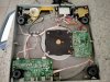
I’ve taken apart my Mitsubishi, added new headshell wiring etc… I don’t understand how it connects to the sound board… I see the left and right channel Caps…

The schematic shows the ground and channel wires go to muting switch, then it looks like it goes to the RCA terminals. Another blue wire goes to ground on board…

it sounds fine, but is that how it connects correctly?
 
Register to hide this ad
Understood. But since the guy has already taken apart the arm and now doesn't know how to connect it to the circuit board, it now is broken, even if it wasn't before.
JStiks - you clearly have the schematic, so why not follow it? I don't see why, if you have correctly wired the arm, there would be a problem. And if the arm wiring was defective, and you needed to rewire the arm, then our comments are beside the point, and I apologize.
There does seem to be an assumption prevalent on the internet that arms inherently need rewiring, that the company that made the equipment (that the owner chose over other equipment) is so incompetent that its work must be repaired, even if it appears to be working well. Leave aside the obvious fact that the people who made the equipment had experience and access to specialized tools, neither of which most consumers have, anytime an arm is taken apart (and even by professionals), there is a chance that the bearings will be misadjusted or damaged. And even done perfectly, there is strong possibility that there will be almost no improvement in the sound (self deception aside). The exception is that minority that are keen to play CD4 quad records who have an arm with high capacitance wiring. So I think it is irresponsible for internet gurus to suggest rewiring as a matter of course.
I will stop ranting now.

 
Understood. But since the guy has already taken apart the arm and now doesn't know how to connect it to the circuit board, it now is broken, even if it wasn't before.
JStiks - you clearly have the schematic, so why not follow it? I don't see why, if you have correctly wired the arm, there would be a problem. And if the arm wiring was defective, and you needed to rewire the arm, then our comments are beside the point, and I apologize.
There does seem to be an assumption prevalent on the internet that arms inherently need rewiring, that the company that made the equipment (that the owner chose over other equipment) is so incompetent that its work must be repaired, even if it appears to be working well. Leave aside the obvious fact that the people who made the equipment had experience and access to specialized tools, neither of which most consumers have, anytime an arm is taken apart (and even by professionals), there is a chance that the bearings will be misadjusted or damaged. And even done perfectly, there is strong possibility that there will be almost no improvement in the sound (self deception aside). The exception is that minority that are keen to play CD4 quad records who have an arm with high capacitance wiring. So I think it is irresponsible for internet gurus to suggest rewiring as a matter of course.
I will stop ranting now.
I appreciate your understanding! I’ve rebuilt the arm, since a hum was a nuisance. Prior owner removed muting circuit, but spliced connections improperly. Upgraded wires and created a better ground connection in the arm.

My question was to understand why the connections bypass the board and connect to the RCA junction. The lt 30 Schematic seems to show this too. I was hoping anyone with experience on this model can confirm this connection.
 
He probably had issues with the mute switch and bypassed it.

The hum was probably from a cold solder if his work was visibly bad enough for you to call it improper.

I'd restore the circuit to the original scheme with alligator clips and test it to see why someone would bypass the mute section as it's pretty useful, and then decide from there where to solder the tonearm leads more permanently
 
Last edited:
Not sure I get your original question - are you asking why the muting circuit isn't on the main board, or why the previous guy skipped the muting circuit, or something else? I think the muting circuit may have been separate to reduce interference, but that's a guess and maybe an irrelevant guess.
I should note that my question about whether the rewiring was needed was off the mark - if the arm had hum, it needed repair, and you apparently solved the problem, so kudos to you. Less congratulation to the previous owner who seems to have botched whatever he intended.
 
Not sure I get your original question - are you asking why the muting circuit isn't on the main board, or why the previous guy skipped the muting circuit, or something else? I think the muting circuit may have been separate to reduce interference, but that's a guess and maybe an irrelevant guess.
I should note that my question about whether the rewiring was needed was off the mark - if the arm had hum, it needed repair, and you apparently solved the problem, so kudos to you. Less congratulation to the previous owner who seems to have botched whatever he intended.
I ran the new leads directly to the RCA JACK posts. No wire brakes. It sounds fine but thought their was an internal sound board it would link to.
 
He probably had issues with the mute switch and bypassed it.

The hum was probably from a cold solder if his work was visibly bad enough for you to call it improper.

I'd restore the circuit to the original scheme with alligator clips and test it to see why someone would bypass the mute section as it's pretty useful, and then decide from there where to solder the tonearm leads more permanently
Once I dismantled the tone arm, I actually Drilled a micro hole in tone arm, tac soldered ground wire, sanded to eliminate any visible changes.. connected wire to ground post RCA JACK board. the question: I thought there was an internal sound board the channels went through, between the cartridge and External RCAs. but it doesn’t look to connect to the board from the schematic. Thanks
 
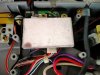
There should be a muting board away from the main board, near the RCAs, likely hidden underneath metal shielding to prevent noise entering the circuit...
 
If it's any help, this is the muting switch circuit board in a little Sony Linear tracker that I'm currently using as a dust-catcher.

Hidden under shielding, close to the output RCAs.


IMG20211007102403.jpg

IMG20211007102408.jpg

IMG20211007102438.jpg
 
There should be a muting board away from the main board, near the RCAs, likely hidden underneath metal shielding to prevent noise entering the circuit...
I can live without the board, just wanted to know is it supposed to go then directly to RCA posts. The muting board in schematic doesn’t show connection to a sound board, just leads to RCA posts….
 
The tonearm wires connect to the muting board, then the signal passes through the muting circuit and onward to the RCAs.

You're getting rid of crap in the way of the signal by going straight from the tonearm to the RCAs, and shouldn't hurt anything.

Muting circuits that activate when tonearms are lowering are nice as you don't get that initial pop when dropping the needle, but most turntables don't have this feature anyway so you're not hurting anything by omitting it.


And the muting board is the sound board.

There is no onboard preamp, phono stage, nothing. All the other circuits are tonearm control, speed control/quartz lock and transport buttons.

Complex little beasts, that sound pretty good for something with what should be a paper-mache platter. So light weight.
 
Last edited:
The oem wiring is very good if a bit long from the muting board. I replaced my arm wiring for being pinched during factory assembly.
 
Back
Top Bottom