• The move to the new server is done. There are some software and database maintenance updates in process. This has us passing the hat around to help out. We appreciate any donations. Seriously, even a dollar helps. The payment page may be found here - https://www.audiokarma.org/support.html

modified magnavox mutt tube amp

Jcricket

not someday, but today
Subscriber
Hey Folks,
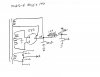
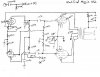
I built this amp from plans I modified from a magnavox schematic. Can I get some opinions on its' designs? It sounds fairly good, but doesn't feel quite right.

Attached are the actual schematics of the amp. I started with a magnavox 8804 chassis. I changed the output transformers to a set of output transformers from Knight kg400(el84 PP integrated) amp. These transformers are UL type instead of the original type used by maggie. I didn't like the sound so I started over. I searched through the internet and found a set of schematics that had similar voltage to what I was reading off the power transformer. The schematic I settled on was the magnavox 142(6v6 PPP) amp. I dropped off the parallel section so this is now a 6v6 PP amp.

Other differences from the 8804 - I changed the rectifier from 6ca4 to a 5y3. The 8804 used 6eu7's, this amp uses the 12ax7's.

On the schematics the values shown are the actual values used and read with my volt meter.

What would you change to improve performance on this unit - anything?

Thanks in advance!

Mark
 

Attachments
  • img031.jpg
    img031.jpg
    67.8 KB · Views: 201
  • img032.jpg
    img032.jpg
    37.1 KB · Views: 104
Last edited:
Register to hide this ad
There may be some improvement to be had, by using the 8802 factory values for the grid-ground resistors on the output tubes (470K, instead of 220K), and using a 47K in place of the 22K to ground, in the side of the output that's providing signal to the paraphase inverter. Having 220K load resistors and 470K plate resistors, limits voltage swing somewhat... 470k load would help a bit. With 6V6s in cathode bias, you can go up to 500K there... 470K is a good value.

Also, that 220 picofarad cap from the plate of the first 12AX7 section to ground, can be a 100pf. That might be limiting HF extension a bit.

One other observation is that you would probably be better served to move the feedback connection, from the cathode terminal of the first 12AX7, to the junction between the 3.3K and 200 ohm resistors. That will reduce the influence of the output transformer "ground" and the feedback resistor, on the bias of the 12AX7.

You'd probably also do better with higher B+. Maybe try a 5V4 in place of the 5Y3. Getting up to about 300-320v on the output tube plates, with a cathode voltage rating of nearer to 22-24v or so, should be a better operating point for those 6V6 output tubes. 6V6s are rugged little bastards, so don't worry about them much. As long as they're not visibly red-plating, of course. :D It might require going up to a cathode resistor closer to 330 ohms (that's what I'd predict would work), per channel. IIRC, Magnavox used 165 ohms for all four output tubes in the AMP175; double that value per channel (which is what would be needed, separating into two cathode resistors, one per channel) gives 330 ohms...

The front end should be completely happy with the voltage increase. Running 12AX7s at 300v or so B+, is just fine... you shouldn't need to change anything there.

One other option I did- but this requires some measurement gear (o-scope, etc) to make sure you do it right- is to put a 50K potentiometer, in place of the 22K resistor to ground in the paraphase. Connect the wiper of the pot to the 12AX7, instead of to the junction between the pot and the 470K. That will allow you do dial in the paraphase gain, so that the "bottom" inverted 6V6 exactly matches the gain of the "top" 6V6. That's what I did with my Loktal Maggie amp... and it got down to only .14% distortion at 90% of max power, on an HP distortion meter, after the pot was properly adjusted...

Regards,
Gordon.
 
Hey Gordon,
Thanks a bunch. I will print out yout suggestions and modifiy this a bit further.

THis is my first pseudo design effort. Everything before was a copy and paste and build. I knew I things that needed attention.

I have the o-scope/distortion analyzer too. I'll see if I can figure out how to use the analyzer. I'll post more results in a bit.
Mark

Edit - would the limitied voltage swings acoount for a loss of dynamics in how it sounds?
 
Gordon hit on two items I was about to mention - limited swing on the driver and more B+ (the 5V4 is rated higher too - 175 mA vs. 125 mA for the 5Y3). The 12AX7 load resistors could be lowered too, though the cathode resistors would go down too. Instead of raising the grid resistors, I was thinking about converting to "floating" or "self-balancing" paraphase inverter by disconnecting the 220K/20K junction from ground and connecting a 100K resistor from there to ground. This may improve symmetry - speaking of which, the paraphase inverter will lose symmetry at low frequencies if equal coupling caps are used - use a smaller value for the "top" one. The small input coupling cap is a GOOD thing, with those small transformers...
 
If you use the 50K pot in place of the 22K resistor in the paraphase... you probably would want to use a 430K or 390K resistor "above" it (instead of 470K, on the "top" output tube), so that the sum of the resistor and the pot wouldn't be higher than 500K. 390K plus 50K is 440K; 430K (preferred) plus 50K is 480K. That's a very close match to the other side (470K on the "bottom"), so that voltage swing would be very symmetric.

Tom's right about the asymmetric coupling caps, feeding the output tubes! The one on the bottom should be at least twice (preferably 3 times or more) as big as the top one. .1uf for the top, and .27uf to .47uf on the bottom, should work just fine. You could go as small as .047 on the top and .22 on the bottom... with 470K load resistors, the f3 would still be plenty low.

EDIT: Oh, one other thing: The cap after the PS choke can be bigger. Might want to try closer to 100uf there. After the choke, you don't have to worry about "spiking" the rectifier. Keep the 40uf cap max before the choke... after the choke, you can go a little wilder with it. :D

Regards,
Gordon.
 
Last edited:
Hey Guys,
Thanks so far. I'll get back to the paraphrase stuff in few. I went ahead and installed hte 470k and 47k resistors. I also replace the 220pf with a 68pf(its what I had). I installeda 5v4 for grins and the circuit didn't seem to like it too much. After awhile the signal made a little pop and then faded away. I turned it off let it sit and turned it back on. Same thing.

I put the 5y3 back in and retested it. This seemed to fix that problem.

BUT, I went to check my voltages again and I had recorded something wrong. The plate voltage on the 6v6's is 268v, the screen(or is it grid) is 272v. Isn't that backwards of where it is supposed to be???

Also, when I was reading your info about hte cathode bias resistor, I realized I hadn't posted all of the info.
This unit is biased through on bias resistor and cap. I don't have two 250ohm 10 watt/50uf caps installed. I can split the channels and certainly do this, but that would changed cap and resistor values, correct?

Thanks again,
Mark
 
screen voltage a bit higher than plate is typical in both UL and pentode-wired configurations. If you look at the construction of the transformer it makes perfect sense. The screen grid tap is closer to B+ than the plate end is. Many schematics actually will show ~5v or so higher on the screens.
 
I vote get rid of the global feedback loop and input caps. :)

Are the input caps mandatory with that form of phase splitter?
 
Are you refering to the .0022uf cap at the input? I put them in, as I understand, to be sure and block any possible dc from the source. Just in case you know..
 
If you have DC coming out of your pre-amp, you have a problem. I've always been told to not use them since they supposedly can affect the sound (change phase maybe?)
 
The transformers are fairly small - better to roll off the low end with an input cap than to drive them into saturation (I would guess they go down to 80-100 Hz at 15W). I have a similar pair - I should measure 'em.

As for running without feedback - sure, in triode mode. UL or pentode needs some feedback to keep distortion down and lower output impedance.
 
A couple things. First, I fixed te problem with the 5v4 rectifier. It wa the amp. I had a bad solder joint with a coupling cap, a bad 12ax7, and one resisotr touching another. I ifxed that and added another 20uf to the PS cap.

It sounds pretty good now.

Tom, you say you have a set of output transformers similar to mine? Do you mean similiar to the knight ul transformers I am running? Since those came out of an EL84 pp set up and are nearly twice the size of the maggie's, I would think saturation would not be a major concern. I also thought maybe they would go a bit lower than the original maggies - maybe 60-70hz.

ANy thoughts?

Mark
 
I would remove that input cap as well. (like you mentioned those output's are larger)
(I'm not a fan of those input caps when they can be avoided)

I would remove the bypass cap on the 12ax7 cathode, and move the feedback junction
to where Gordon suggested between the upper and lower resistor, I would also raise the
feedback resistor to say like 4.7k or so, you won't need a lot of feedback with 6V6 an UL.
(dropping that bypass cap on the drivers cathode should bring sensitivity more in line to)

I would also want more voltage like mentioned, and run the 5V4 or even an 5AR4 rectifier.
(not to mention there indirectly heated rectifiers)

I would also add 1-2k screen grid resistors, for stability an dropping some voltage off there.

Also with Gordon there, the cap after that choke, parallel say another 100uf with that 40uf.

Also if that's 100k for the RC stage front end 10K would be just fine here, no voltage worries.

---------------

;)
Personally I'd redo that entire driver section, to an voltage amp direct coupled to Concertina
splitter, if not I'd at least run a 12at7 version of the floating para-phase verse the 12ax7 non.

But hey you're learning and experimenting, have fun an try a few things...:thmbsp:
 
Hey Kegger, thanks fore the feedback. Just to be sure I understand you:

One, remove the 20uf cap that is parallel with the 3.3k resistor? JUnction has been moved.

Two, 2.7 to 4.7 k - done

Three - will do when the rest is complet. I'll measure voltage then and see where I am at.

Four, I think you are saying to run 1-2k resistord from pin four of the 6v6 to ground, just to bleed off a little voltage from the screens/grids. Correct?

Five - will be done shortly.

Six, change the 100k resitor that gets the b+ for the front end to 10k? Can do no problem.


I think I have it. I'll look up that other front end desiogn you mentioned and see what it looks like. But for now, I gotta get it running well.

Thanks again,
Mark
I would remove that input cap as well. (like you mentioned those output's are larger)
(I'm not a fan of those input caps when they can be avoided)

One I would remove the bypass cap on the 12ax7 cathode, and move the feedback junction
to where Gordon suggested between the upper and lower resistor,

Two I would also raise the
feedback resistor to say like 4.7k or so, you won't need a lot of feedback with 6V6 an UL.
(dropping that bypass cap on the drivers cathode should bring sensitivity more in line to)

Three I would also want more voltage like mentioned, and run the 5V4 or even an 5AR4 rectifier.
(not to mention there indirectly heated rectifiers)

Four I would also add 1-2k screen grid resistors, for stability an dropping some voltage off there.

Five Also with Gordon there, the cap after that choke, parallel say another 100uf with that 40uf.

Six Also if that's 100k for the RC stage front end 10K would be just fine here, no voltage worries.

---------------

;)
Personally I'd redo that entire driver section, to an voltage amp direct coupled to Concertina
splitter, if not I'd at least run a 12at7 version of the floating para-phase verse the 12ax7 non.

But hey you're learning and experimenting, have fun an try a few things...:thmbsp:
 
With the help I ma getting and how nice this amp is starting to sound, I might just go ahead and order some edcor outputs. I gotta measure to see if they fit, but heck,. I think this amp could justifiy the expense. It would be cool to see how those edcors perform too. I could put them on the o-scope and post some results too.

I am looking at the 25w 8k 4,8,16 ohm from 20-20k versions.
 
"Four, I think you are saying to run 1-2k resistord from pin four of the 6v6 to ground, just to bleed off a little voltage from the screens/grids. Correct?"

NO, those resistors are in series with the UL taps.

So you go from pin 4, 1-2k resistor (right at the pin) then wire the other side of the
resistor to the UL tap, so the voltage goes through that resistor from the tap to pin.
 
With the help I ma getting and how nice this amp is starting to sound, I might just go ahead and order some edcor outputs. I gotta measure to see if they fit, but heck,. I think this amp could justifiy the expense. It would be cool to see how those edcors perform too. I could put them on the o-scope and post some results too.

I am looking at the 25w 8k 4,8,16 ohm from 20-20k versions.

Being as though the outputs you have now have UL taps, I'm inclined to stick with them.
Generally if the manufacturer took the time to tap them, they tend to be quality outputs.

I'd run with those an not think about upgrading. Probably quite nice..:thmbsp:
 
Also, when I was reading your info about hte cathode bias resistor, I realized I hadn't posted all of the info.
This unit is biased through on bias resistor and cap. I don't have two 250ohm 10 watt/50uf caps installed. I can split the channels and certainly do this, but that would changed cap and resistor values, correct?

There's two ways of thinking about this.

One, is by separating them, you can use matched pairs of tubes, rather than having to use a matched quad of 6V6s. That's a convenience.

The other, was brought up by Dave Gillespie, in his test of the Dynaco SCA35. Sometimes, the amp can have lower distortion, with both channel's output tubes on ONE cathode resistor and cap. This makes the amp act in a "semi-fixed bias" mode... it prevents a big draw on one tube, from shifting the bias point nearly as much in the short term, as having just two tubes per cathode resistor. In effect, you have THREE other tubes 'regulating' each one, rather than one trying to 'regulate' one...

I've done most of my small cathode-bias amps with one common resistor and one cap... they certainly have sounded very good so far...

If you use one common resistor for both channels, it should probably be around 160 or 170 ohms. As I mentioned, Magnavox used a 165 ohm resistor on the AMP175- that's a very good starting point. That, with a 220uf (slightly bigger or smaller OK) or so cathode cap, should take care of business. You're trying to get a total of about 140-150ma of idle current through the four tubes, together... with a 160 ohm resistor, 24v at the cathodes would be just about right. If it's higher than that, go up in resistance. If it's lower, but at least 22v, leave it alone... it will be fine.

Regards,
Gordon.
 
Hey folks,
I did the mods and came up woth the following voltages.

B+ is now 315v - with 5v4 rectifier
Bias is at 24 volts
pin three plate is 309
pin 4 grid is 312

I removed the caps on the input, changed the 100k to 10.2k, added a 1k in series with the pin 4 grid,removed the 20uf on the cathode bypass of the 12ax7's, and added 220uf to the ps capacitance.

There may be afew mods I missed listing, but I did everything discussed so far. It sounds really good too.

On the cathode bias resistor, I had a 250 ohm in there. I paralleled a 2k with 400 ohm to get my voltage where it needed to be. I suspect something like 330 ohms would have been right.

Now it is time to hook up some speaekrs and let her play while I clean up the bench for the next project.

I owe you folks - again!:thmbsp:

Thanks,
Mark
 
Back
Top Bottom