genlabs
New Member
It has been a while since I shared one of my projects on here.
This is the last thing I completed.
It revolves around the SAE P102. It is probably one of the least loved of the vintage SAE pieces.
Not because of its sound signature. Was there better sounding? Of course there was but this device was trying to meet a price/performance point using some cutting edge 80's technology. I think it sounded great! It tried to bring a high end look and feel to modestly priced HiFi systems. It was just too ahead of its time when it was introduced in the early 80's. The futuristic lines and purely digital controls turned many consumers, who favored knob spinning, off.
So fast forward to today. I have a collection of this gear and I still think it sounds great, especially if it has been maintained. One thing the 02 series never offered was Remote Control! . The D102 CD player, which was based on a highly praised Magnavox chassis, was the exception, which came with a simple remote. I don't know if eliminating remote control was a cost cutting measure. I can see how the CPU and IC's driving the user interface and logic would have been an expensive commodity in the 80's, driving up the overall cost of the device. It seems silly that a futuristic design would opt to leave out such an important feature. This is a record of my journey to change that.
I was on a mission to add remote control capability to my beloved P102. I was not looking to control all the functions. I just really need Power, Mute, Vol +/-, Bass +/- & Treble +/-. I use the pre-amp exclusively with a Schiit DAC so I don't change inputs often. The following is what I came up with and it has been installed inside the P102 enclosure. Inside is a Arduino Nano, a 8 channel relay board and a small buck-boost regulator. The relay board emulates button presses. I will jump wires to each button on the P102. If I wanted to control more buttons I could just swap in a 16 channel relay board.
NOW HOLD ON!!...before people start going bonkers and begin flaming this thread because there are "easier" ways to do this let me just say this: a) these vintage SAE components used a lot of trickery to save money and limit integrated circuit complexity. For example each button is not merely grounded to activate a function. Each button works in a XY matrix AND each button also shares a common Anode switching line with each 8 segment LED. It was a rather complex problem solved by some nifty engineering. I could generate my own pulses to emulate the XY scan presses but that is programming intensive and requires me poking wires directly onto CPU decoder lines. That's all fun and games until you blow up a vintage CPU chip when you zigged instead of zagged. b) Cost and time; I did not want to code hundreds or even thousands of lines of code for such a simple idea. I did not want to use more complex controllers. The Arduino Nano, at under $5 each, is a perfect choice. c) Isolation; the relays give me galvanic separation and are nothing more than electrically controlled switches. There really is no way to mess things up. The brute force approach seems fine for this particular application. Okay now that's out of the way ....let's continue.
I robbed some HEX codes from a Dish Network remote I found. I pulled the HEX codes by watching the Serial Monitor of the Arduino and copied those codes to a notepad. I don't use Dish so there wont be any cross contamination of remotes but I really could have used any obscure remote control. After I captured 8 different HEX codes I assigned one of them to each of the relays. Each relay pulses for about 200 milliseconds when commanded. Holding a key on the remote causes the expected repeat-ability behavior. Power consumption by the Arduino Nano and Relay Board is minuscule and power will be tapped from an existing 12 volt DC line on the P102 main board, which is before its own on-board voltage regulators. The 12 volt line is fed to a separate tiny buck-boost regulator (this was probably unnecessary, but I sleep better at night with it there).
I have posted a video of it in operation on YouTube. It can be seen here:
These photos also show some of the construction phases:
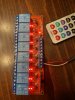
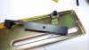
The 4 parts: Relay board, Arduino, Buck Regulator, IR Phototransistor

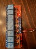
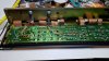
Wires waiting to be attached

Add photo transistor to internal bezel

Final terminations

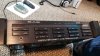
Fully re-assembled

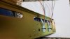
New IR photo transistor visible in window. Ready to sit back and enjoy long distance control.

See YouTube video above to see it in operation.
In the future I may print up a smaller board using reed relays for totally silent operation.
This is the last thing I completed.
It revolves around the SAE P102. It is probably one of the least loved of the vintage SAE pieces.
Not because of its sound signature. Was there better sounding? Of course there was but this device was trying to meet a price/performance point using some cutting edge 80's technology. I think it sounded great! It tried to bring a high end look and feel to modestly priced HiFi systems. It was just too ahead of its time when it was introduced in the early 80's. The futuristic lines and purely digital controls turned many consumers, who favored knob spinning, off.
So fast forward to today. I have a collection of this gear and I still think it sounds great, especially if it has been maintained. One thing the 02 series never offered was Remote Control!
. The D102 CD player, which was based on a highly praised Magnavox chassis, was the exception, which came with a simple remote. I don't know if eliminating remote control was a cost cutting measure. I can see how the CPU and IC's driving the user interface and logic would have been an expensive commodity in the 80's, driving up the overall cost of the device. It seems silly that a futuristic design would opt to leave out such an important feature. This is a record of my journey to change that.I was on a mission to add remote control capability to my beloved P102. I was not looking to control all the functions. I just really need Power, Mute, Vol +/-, Bass +/- & Treble +/-. I use the pre-amp exclusively with a Schiit DAC so I don't change inputs often. The following is what I came up with and it has been installed inside the P102 enclosure. Inside is a Arduino Nano, a 8 channel relay board and a small buck-boost regulator. The relay board emulates button presses. I will jump wires to each button on the P102. If I wanted to control more buttons I could just swap in a 16 channel relay board.
NOW HOLD ON!!...before people start going bonkers and begin flaming this thread because there are "easier" ways to do this let me just say this: a) these vintage SAE components used a lot of trickery to save money and limit integrated circuit complexity. For example each button is not merely grounded to activate a function. Each button works in a XY matrix AND each button also shares a common Anode switching line with each 8 segment LED. It was a rather complex problem solved by some nifty engineering. I could generate my own pulses to emulate the XY scan presses but that is programming intensive and requires me poking wires directly onto CPU decoder lines. That's all fun and games until you blow up a vintage CPU chip when you zigged instead of zagged. b) Cost and time; I did not want to code hundreds or even thousands of lines of code for such a simple idea. I did not want to use more complex controllers. The Arduino Nano, at under $5 each, is a perfect choice. c) Isolation; the relays give me galvanic separation and are nothing more than electrically controlled switches. There really is no way to mess things up. The brute force approach seems fine for this particular application. Okay now that's out of the way
....let's continue.I robbed some HEX codes from a Dish Network remote I found. I pulled the HEX codes by watching the Serial Monitor of the Arduino and copied those codes to a notepad. I don't use Dish so there wont be any cross contamination of remotes but I really could have used any obscure remote control. After I captured 8 different HEX codes I assigned one of them to each of the relays. Each relay pulses for about 200 milliseconds when commanded. Holding a key on the remote causes the expected repeat-ability behavior. Power consumption by the Arduino Nano and Relay Board is minuscule and power will be tapped from an existing 12 volt DC line on the P102 main board, which is before its own on-board voltage regulators. The 12 volt line is fed to a separate tiny buck-boost regulator (this was probably unnecessary, but I sleep better at night with it there).
I have posted a video of it in operation on YouTube. It can be seen here:
These photos also show some of the construction phases:
The 4 parts: Relay board, Arduino, Buck Regulator, IR Phototransistor
Wires waiting to be attached
Add photo transistor to internal bezel
Final terminations
Fully re-assembled
New IR photo transistor visible in window. Ready to sit back and enjoy long distance control.
See YouTube video above to see it in operation.
In the future I may print up a smaller board using reed relays for totally silent operation.
Attachments


Last edited: