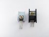
I have the power amp AWH-033 in front of me and want to change all the transistors Q1 until Q10. The 4 Output Q11 – Q14 shall stay at this stage.
I use the BOM list for the SX-737 and everything was fine until I came to the Q7 - Q10. Original installed are 2sd357 and 2sb527 and I have ordered the recommend replacement SC2690 and SA1220.
The issue here are the pins. The old ones are BCE pinout and the new ones have ECB pinout. Normally that not a big deal to bring the legs into the right position, but these four transistors are mounted on big heat sink which have to sit at a special position on the board, due to limited space around.
With the changed leg position on the new transistors it is nearly impossible to mount the transistors on the heatsink crossing the legs E and B without risking a contact between all tree pins.
One could mount the transistor backwards, that will bring the legs into the right position, but then you have the metal side not in contact with the heatsink and even worse, it makes it impossible to read the part number.
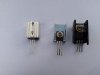
We talking about the four U-shaped black heat sinks on that picture.

What are your recommendations on these issue and how can I solve it, still having a good heat dissipation.are
There will be a similar challenge on the power supply board with the q3 2sd313, replaced by a SC2073 if it's not a BCE pinout.
I use the BOM list for the SX-737 and everything was fine until I came to the Q7 - Q10. Original installed are 2sd357 and 2sb527 and I have ordered the recommend replacement SC2690 and SA1220.
The issue here are the pins. The old ones are BCE pinout and the new ones have ECB pinout. Normally that not a big deal to bring the legs into the right position, but these four transistors are mounted on big heat sink which have to sit at a special position on the board, due to limited space around.
With the changed leg position on the new transistors it is nearly impossible to mount the transistors on the heatsink crossing the legs E and B without risking a contact between all tree pins.
One could mount the transistor backwards, that will bring the legs into the right position, but then you have the metal side not in contact with the heatsink and even worse, it makes it impossible to read the part number.
We talking about the four U-shaped black heat sinks on that picture.
What are your recommendations on these issue and how can I solve it, still having a good heat dissipation.are
There will be a similar challenge on the power supply board with the q3 2sd313, replaced by a SC2073 if it's not a BCE pinout.
Last edited: