• The move to the new server is done. There are some software and database maintenance updates in process. This has us passing the hat around to help out. We appreciate any donations. Seriously, even a dollar helps. The payment page may be found here - https://www.audiokarma.org/support.html

MR71 Transformer (043-344) Extra Coil?

Johnny_Law

o.O
Subscriber
Hi All -

Maybe a quick answer to this, but I couldn't find it searching through old threads ...

My MR71 is cosmetically challenged, and the transformer case is all rusted out. I picked up a good looking 043-344 from someone parting out an MR71.

Going to swap them, I am confused as I've found an extra pair of leads which are continuous in the replacement transformer. Can anyone tell me where these go?

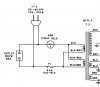
Here's the schematic of the MR71 power supply (this seems to be consistent from early MR71 which use T123-133A transformers to later MR71 which use 043-344, although I can't find the serial number for the change) ... my serial # is 43B00:
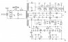
MR71 Power Supply.jpg

Here's my original transformer in situ:
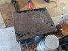
PXL_20220313_001112254.jpg

Note that there is only 1 pair of black leads, which go to the AC power input:
PXL_20220313_001214114.jpg

Here's the replacement:

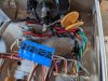
PXL_20220313_001121786.jpg

Note that there are 2 pairs of black leads ... there is continuity across the plain black to white striped leads, and continuity across the red striped to green striped leads (hard to spot the green in the pic).

PXL_20220313_001147261.jpg

So the question is ... in the replacement transformer, which pair of black leads do I hook up to the AC input? Where do I put the other pair? Did I get the wrong transformer?

Thanks!
 
Last edited:
Register to hide this ad
I'll take a wild, wild guess and say that the primary can be changed from 120 VAC to 220 VAC. A series connection of the wires goes one way, a parallel connection goes the other. I do not know how to figure out the wiring.
 
Looks like you have two black and two black with white stripe wires. I'd try tying the black to black, black/white to black/white which will hopefully put the primary windings in parallel with the proper phasing, and the 120V input connected to the two tie points. I'd check secondary voltage BEFORE you install it. If it's zero, then the primaries are out of phase. If the voltage is half what it should be, then the primaries are in series.
 
Thanks - I wish there was two black but there's only one black. The others are black with stripes (white, green, red). The black and white are continuous and the red and green are continuous.

I suppose the same could apply nonetheless.

Maybe if I take off my current transformer I'll find another pair of wires looped under the cover?
 
Well that makes it harder but not impossible.You can try tying black and black/red together, and black/white and black/green together, and quickly connect it temporarily to 120V (preferably thru a dim light bulb tester) while monitoring one of the secondary windings with a voltmeter. As I mentioned above - zero is bad, it means the primaries are out of phase and pull the plug ASAP.

However, you should be able to get away with just ignoring the second set of primaries - just connect to black and black/white and cap off the other two.
 
Put 6.3 volts AC on one of the 6.3 volt outputs, and measure what's going on. Use a variac to drive your 6.3 volt ac source and start at 25%.
 
I don't have a variac. So, should 6.3V into the one winding result in 120V out of the correct input winding?
 
Hello

This power transformer is a very rare 220v power transformer for MR71 !
Quasi impossible to find "new" like this one

MCINTOSH Labs never produced 220v MR71 Power transformer with primary silk screening in 220V !
 
This inspired me to pick up a variac, so now I have one and I'll see if one of those black lead pairs shows 220V with 6.3V input into the correct leads.
 
They may both show 120 volts and you have to tie them together in series to get 240 volts.
 
You are right
a power transformer work in two ways
if you connect 6,3V at the brown wires do not exceed 500mA
But as I said previously this is an "export version " with double 110V primary
One primary is
Black / Black white (110V)
The other one is :
Black / Black red (110V)
 
Put 6.3 volts AC on one of the 6.3 volt outputs, and measure what's going on. Use a variac to drive your 6.3 volt ac source and start at 25%.

You are right
a power transformer work in two ways
if you connect 6,3V at the brown wires do not exceed 500mA
But as I said previously this is an "export version " with double 110V primary
One primary is
Black / Black white (110V)
The other one is :
Black / Black red (110V)

Quick question about using my variac. I got a W5MT 5amp variac. It has one knob for voltage, but no adjustment for current. Should I not use this because I can't limit the current?
 
You will have to "phase" the 120v coils correctly to use them in parallel as shown. If they are out of phase, magnetic fields generated will be opposite and cancel out, generating no output and drawing a lot of primary current.
 
Connect as in the diagram above, run it on a 15w DBT, measure everything and if good you got it right.

I have a variac, hardly ever use it but always use the DBT.
 
Back
Top Bottom