• The move to the new server is done. There are some software and database maintenance updates in process. This has us passing the hat around to help out. We appreciate any donations. Seriously, even a dollar helps. The payment page may be found here - https://www.audiokarma.org/support.html

MR80 display ranging

I put @Gregory ’s MR80 into my basement shop system a couple of weeks ago. I have an antenna feed for my receiver down there to an attic antenna. There was some scrolling but I was able to lock in stations. SQ is very good. All functions worked as expected. After a few days of using it, the scrolling returned. I tried swapping the plug polarity and changing the fast/slow scan function. There is an audible click as the the LED scrolls.

Today I opened it up and unplugged the RCA. The scroll slowed up bit hear the presets but continued to run…..so I may have matched my skill set on this diagnosis. I will power down, wait a bit then reseat the IC’s to try again.
Definitely sounds a lot like what mine would do. I'd go ahead and replace the LO transistor.
I reseated IC's until I was blue in the face, and every time I did it I thought, "oh thats better", only to have the same symptom return.
The more you use it and the longer its on, the worse it will get.
 
Theres not really anything there that relates to the scrolling issue, the area where you want to look at is in the sliver box, thats where all the display driver IC's are, take the lid off and reseat all those, but I think its futile...its a noisy signal coming from the LO+IF stage. The transistor I am talking about is the area of concern.
But the other thing you could look at is the Grey RCA cable that takes the signal from the IF to the sliver box where the display driver IC's are, if that connection is not good, or the connections are dirty of intermittent, it could show that symptom.
I did a thorough cleaning of the RCA connector and plug. I will take a look into the IF area. Besides the screws it looks like the cover is snapped in tightly. I am taking my team review his schematics and these posts. Thanks again for your support.
 
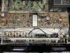
Bottom cover off. Cleaned this part of the RCA jack and connector. Reseated the cable connectors and ICs. Still ranging with very audible clicking while digital display is ranging.

I need help to identify the q205 transistor on the correct board. Thanks

IMG_0460 Large.jpeg

IMG_0461 Large.jpeg
tempImage2GYVVF.png
 
You need to turn the unit over, the IF board is on the topside.
Let me get my MR80 on the bench and take some pictures, it will make things so much easier.

Do you have the complete MR80 service manual?
 
Here is all you need to know.
Circuit diagram and circuit board layout.
You'll need to take the cover off the IF board, You may need to desolder a couple of wires.
On the board layout, look to the left of T201(3rd bay from the right) and you'll see Q205.
Let me know if you need more help, note the pinout of the new transistor is different, but because the holes are triangulated its easy to fit it.
It's not hard to remove the board.

Screen Shot 2022-03-30 at 9.07.27 AM.png Screen Shot 2022-03-30 at 9.08.05 AM.png
 
Got it. Just the support I need. Without Greg, its deep water. But your help is appreciated. Will get back on top side and remove the IF panel. I am comfortable desolder and soldering. Thanks
 
You need to turn the unit over, the IF board is on the topside.
Let me get my MR80 on the bench and take some pictures, it will make things so much easier.

Do you have the complete MR80 service manual?
yep, he kept track of the recap job he did preciously and kept the service manual albeit in separate 8.5 and 11 inch printouts.
 
Got it. Just the support I need. Without Greg, its deep water. But your help is appreciated. Will get back on top side and remove the IF panel. I am comfortable desolder and soldering. Thanks
Cool, looks like you have the necessary documentation, just reach out if you need a hand.
 
ok, have the three pages of schematic opened for this section. Working through the diagram to identify the part. I will remove the board later today. Thanks

MR 80 RF IF.jpg
 
Got it. Just the support I need. Without Greg, its deep water. But your help is appreciated. Will get back on top side and remove the IF panel. I am comfortable desolder and soldering. Thanks
Hey, another favor. Any way you can enlarge the PC board layout image? I can't get a reasonable sized copy for my eyes.
thanks!
 
Update - I felt uncomfortable doing the desolder on the transistor. @cawgijoe fortunately has a neighbor that is an RF engineer. I took him the service manuals, schematics and Greg's notes. He has an interesting workshop with more test gear than I have seen in one place (for his day job). Anyway he reported out this status - first test was cold spray - no effect.

Second test was to look at the osc output: I connected a scope to the output from the IF module (at the RCA jack). Not sure what I was expecting to see, but here is what I see:
  • Frequency is reasonably stable. No surprise here since I can listen to a station and it comes in clear. Though the display is moving all over the place, the LO is not.
  • There is a little frequency variance; this shows up as some jitter; I suspect this is due to AFC, tracking, modulation, and the PLL
  • The osc output is not as well shaped as I had suspected but it is not bad.
  • P-P voltage is several 10s of mV. Not sure what it is supposed to be. Can you ask on audio karma?
I am mystified by the fact that the scan digital reading is all over the map but the LO is stable. I wonder if you could ask the AudioKarma point of contact if that was his experience also.

My next step was to poke around on the frequency counter board (underside, with its own nice EMI cover).
  • I really expected the input to IC104 to look very digital but it looked like a low amplitude triangle wave superimposed on a DC signal.
  • I think the purpose of IC101 is to amplify and essentially limit the local osc input so that it looks like a digital signal by the time it gets to IC102. This does not appear to be happening.
    • Jameco has this in stock for a $1.05. I think mouser did not have it.
  • Under the theory that the problem is signal level or noise from q205, I pulled it. It measured OK: gain 91, Vbe 08.52. Replacement had gain 131, same Vbe. Both were within spec.
    With new transistor, receiver still receives, and display still scrolls out of control.

    BTW with bottom cover off I can hear reed relays click every sec or so: there are reed relays on the scan ctl board. That may be a consequence of the scanning. This may be k304, which speeds up the scan for frequencies > 100 MHz. The scan speedup signal comes from the display, so while running away, depending on when it crosses 100 MHz, K304 will be activated or not. Still, since the station sounds fine, the LO is not changing.
    • The actual scanning seems to work, in that I can hear station x, it the scan to next, then hear the next station.
 
More update - "Got it!"
He reviewed section 10 with test notes.

These suggested the counters/flip flops were ok but the signal was getting lost between the input to the frequency counter module and IC 103.

Looked carefully at IC 101 and 102; all are socketed. Noticed 101 is a ceramic package (not sure if it needed to be: it is really low power part). Noticed also that the pins look less than shiny new; pushed on the pins individually. Didn’t think it would matter. Powered up the receiver and display was correct!

So this is an IC socket/seating problem on IC 101.

IC 101 is “under” a choke; even though it is socketed the choke probably has to be removed and re-soldered when done. I recommend replacing the part; either the pins on the part or the socket are a little unreliable. Replacement part ordered.

Hope this helps any other MR 80 owner.
 
Thats a bummer it wasn't as simple as mine. There is also another transistor that could be an issue, its the mixer stage which adds the IF frequency to the received frequency, it might be Q204 (havent got the schem in front of me) but that will also cause issues if its weak.
The other thing you can do is look at the 5V supply, if there is any issue or any sort of noise on this supply, it can also affect the display.

If your neighbor has an RF gen, you could drive the display with the RF Gen, this is what I did to narrow the issue down.
Once I was driving the appropriate signal level into the display driver circuit via the RCA connection, I could see the display was stable and worked back into the IF section from there.
You could do the same but it may be that the problem is in the display driver stage.

Just remember you need to add 10.7mhz to whatever frequency you want to display, so for 100mhz, you need to inject 110.7mhz and so forth.

What part do you think needs replacing? Not sure I got that from the notes above?
So you have the display working now?
thanks, Kev, I will pass on your notes.

He said after reseating IC 101 and102, which he noted 101 was not shiny, the display stayed on the programed station. Just in case he wants to replace IC 101. He thought the pins were not reliable.
 
thanks, Kev, I will pass on your notes.

He said after reseating IC 101 and102, which he noted 101 was not shiny, the display stayed on the programed station. Just in case he wants to replace IC 101. He thought the pins were not reliable.
Yes sometimes the tarnish will creep down the legs and interfere with the connections.
Reseating the IC's on my unit changed nothing. But its good to do anyway.

The MR80 is a very complicated unit so really, its hardly surprising the same symptom is driven by a different fault.

I am sure this thread will be a great resource should others have issues.
 
Here is an update from Tim last night -


the maint/repair manual section 10 said short the input to the freq counter and observe the count; also remove one of the ICs (104) and observe the count.

It was late last night but I think the first test failed but the 2nd test worked. This suggested input components on the freq counter board. I considered injecting a sign gen source into the freq counter but didn’t find the specs for it until after the tests above suggested that the problem was u101 or u102.

Replacement u101 part will arrive Sat. The one in the unit is probably fine except in that socket it is likely to work its way out and become loose again. I didn’t pull it out to see if there was a bent or compromised pin but there may be; best to replace it (and it is a $<2 part).
 
Back
Top Bottom