• The move to the new server is done. There are some software and database maintenance updates in process. This has us passing the hat around to help out. We appreciate any donations. Seriously, even a dollar helps. The payment page may be found here - https://www.audiokarma.org/support.html

Mullard 5-20 High Frequency oscillation

coylum

Well-Known Member
As mentioned in previous threads I have just constructed the first of two Mullard Twenty Watt amplifiers using Transcendar output transformers similar to ones which I have successfully used previously in the Mullard 5-10 circuits.

When checking sine and square wave response I discovered a resonance peak at 79KHz and some ringing on the 5KHz square wave which was largely removed by increasing the NFB network capacitor C9 from 330pF to 398pF. During this process I also ran the amp with no NFB compensating capacitor and oscillation, at 79KHz, occurred with no input and the gain control turned to zero. The oscillation had a magnitude of around 4.8v rms across an 8Ω resistive load. I found this very worrying as it indicates a major potential for instability even when the NFB compensation capacitor is in place?

I would appreciate comments and advice on how to address this issue so as to have an adequate stability margin. Ideally I want to stay as close as possible to the original Mullard specification but equally I do want to make these Transcendar OPT’s function correctly with a margin of safety.

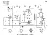
I have detailed below in chronological order the tests and adjustments I have made so far – I have also attached the schematic.
  • Negative feedback: -30db specified; Measured open loop gain 64.7dB – Closed loop 35.4dB Actual NFB using 5.6KΩ/330pF equals 29.3dB
  • Frequency response: 1 watt, open loop -2dB points 50Hz to 10KHz; Closed loop (5.6KΩ/330pF) ±0.25dB 10Hz to 20KHz, -1.6dB at 100KHz but with small peak at 80KHz +0.7dB.
  • Square wave performance: With NFB 5.6KΩ/330pF 5KHz – ringing evident both top and bottom. Increasing to 398pF appeared to remove ringing (see later) but frequency response dropped to -0.5dB at 20KHz (was -0.25db) and -3dB at 100KHz. The resonant peak seemed to have gone.
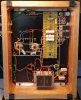
  • Two adjustments made to layout and component values elsewhere: The EL34 cathode capacitors were relocated from the tagboard to direct pin connections on the valve bases to remove them from the heat of the cathode resistors. The relative values of R12 and R11 were adjusted to make R12 nearly 3% higher than R11 yet still within 5% of the nominal 180KΩ value (183KΩ and 178KΩ respectively) as this is suggested for optimal balance by Mullard.
  • Whilst preparing to finalise frequency response readings with 5.6KΩ/398pF NFB compensation I noticed the ringing on the 5Khz square wave was back as well as the resonant peak at 80KHz. Could the above mods cause this?
  • Whilst preparing to further increase C9 I observed that with no capacitor in place the amplifier was oscillating at 79KHz with no input and the gain control set to zero. The oscillation had an amplitude of 4.8V rms across 8Ω resistive load and increased in amplitude if the gain control was advanced.
At no point as any change been made to C1/R3 on the anode of V1 – they have remained throughout as originally specified.

Malcolm
5-20 Schematic.jpg Underside.jpg
 
Register to hide this ad
Just a sanity check, all this NFB is applied in a single loop. And its magnitude is effectively 30 dB.

Now consider the Citation II, with arguably a top 5 *EVER* set of OPT's and they sported 32, and part of it was in two nested loops across the front end...

So what do you think you ought to do?
cheers,
Douglas
 
That's a really beautiful and well done build. As a statement of fact, a pretty special output transformer is required to apply 30 dB feedback and have an unconditionally stable amp as a result. I suspect, as good as the Transcendar output transformers are, they cannot deal with 30 dB global feedback on this circuit.

This is going to sound invasive, but here's what I'd consider doing:
1. Try first removing the cathode bypass cap on the EF86 cathode and reducing feedback to under 20 dB (say 15 to 18 dB), with feedback cap adjusted to compensate.
2. If oscillation remains, try rewiring EF86 in triode mode and reducing feedback to say 14 dB with feedback cap adjusted to compensate
3. If oscillation remains, try playing with the numerical values of the components in the step network (look like C1 and R3 in schematic, can't quite tell if those are the lables)--the series cap/resistor in parallel with the EF86 plate resistor. In fact, in any of the above two cases, the step network will likely need to be adjusted anyway. It is a handshaking tradeoff exercise to obtain decent frequency response and stability with the feedback cap vs. the step network. Both need to be adjusted together.

So...unfortunately you may be in that situation where you can't just follow the schematic wholesale. You may be forced to reduce feedback and tune the amp yourself precisely because you are not using the exact same transformers as was used in the original 5-20. Amp tuning is highly dependent on the output transformers used. I know...you already know that...but now you are probably seeing the evidence of this first hand.

It is not trivial to get a feedback amp stable. Not only does it need to be stable under resistor dummy load, but it needs to be stable when you hook up odd-ball speaker impedance loads. Worst case can usually be tested in a dummy speaker load of a single capacitor hung between the speaker terminals, of say 0.05 uF to about 5 uF.
 
Last edited:
Just a sanity check, all this NFB is applied in a single loop. And its magnitude is effectively 30 dB.

Now consider the Citation II, with arguably a top 5 *EVER* set of OPT's and they sported 32, and part of it was in two nested loops across the front end...

So what do you think you ought to do?
cheers,
Douglas

Yes, the elephant in the room is obviously the high feedback and no doubt I will need to make changes. The high NFB is a feature of the Mullard amplifiers and they must have had very good OPT's? I have two Mullard 5-10's using Transcendar OPT's (same model just different impedance) and they are totally stable with 26dB single loop NFB. I had hoped I could duplicate this in the 5-20 :(
 
That's a really beautiful and well done build. As a statement of fact, a pretty special output transformer is required to apply 30 dB feedback and have an unconditionally stable amp as a result. I suspect, as good as the Transcendar output transformers are, they cannot deal with 30 dB global feedback on this circuit.

This is going to sound invasive, but here's what I'd consider doing:
1. Try first removing the cathode bypass cap on the EF86 cathode and reducing feedback to under 20 dB (say 15 to 18 dB), with feedback cap adjusted to compensate.
2. If oscillation remains, try rewiring EF86 in triode mode and reducing feedback to say 14 dB with feedback cap adjusted to compensate
3. If oscillation remains, try playing with the numerical values of the components in the step network (look like C1 and R3 in schematic, can't quite tell if those are the lables)--the series cap/resistor in parallel with the EF86 plate resistor. In fact, in any of the above two cases, the step network will likely need to be adjusted anyway. It is a handshaking tradeoff exercise to obtain decent frequency response and stability with the feedback cap vs. the step network. Both need to be adjusted together.

So...unfortunately you may be in that situation where you can't just follow the schematic wholesale. You may be forced to reduce feedback and tune the amp yourself precicely because you are not using the exact same transformers as was used in the original 5-20. Amp tuning is highly dependent on the output transformers used. I know...you already know that...but now you are probably seeing the evidence of this first hand.

It is not trivial to get a feedback amp stable. Not only does it need to be stable under resistor dummy load, but it needs to be stable when you hook up odd-ball speaker impedance loads. Worst case can usually be tested in a dummy speaker load of a single capacitor hung between the speaker terminals, of say 0.05 uF to about 5 uF.

Thank you for such a detailed response

I guess I have no option but to go down the track you suggest or something very similar. The primary reason I was trying to stay as close to the original as possible was to maintain the low distortion performance that this particular amplifier was known for. I can measure frequency response and fine tune stability but I have no facility to check the results on distortion.

I am unclear as to how the step network interplays with the feedback capacitor but I guess I'll learn as necessary....

At least when I get this prototype correctly tuned It should be plain sailing with the second one!

Cheers, Malcolm
 
Right. It will become obvious the first time you try adjusting values. You've already seen some of those effects--larger feedback cap reduces HF bandwidth. You will also notice it changes square wave shape which is just another way to visualize HF performance.

A larger cap in the step will also reduce HF bandwidth, hence the "handshaking" I was referring to. The resistor in the step limits the gain reduction at higher frequencies thus also affects bandwidth. Best way to get a feel for it all is to just experiment and watch how square wave shape changes and how bandwidth changes.

If you're starting from scratch, I.e., no schematic as a starting point, I like to set initial step values to 10k ohms and 100 pF and then adjust from there. My preference is to make the feedback cap as large as you can get away with first, without the step network engaged, and without increasing the slant of the square wave sidewalls, then add the step to fine tune the HF response from there.

I've got some pics of HF tuning steps visualized through square wave shape, adding one component at a time--at first just feedback resistor, then feedback cap, then step. I'll see if I can find them.
 
Last edited:
Right. It will become obvious the first time you try adjusting values. You've already seen some of those effects--larger feedback cap reduces HF bandwidth. You will also notice it changes square wave shape which is just another way to visualize HF performance.

A larger cap in the step will also reduce HF bandwidth, hence the "handshaking" I was referring to. The resistor in the step limits the gain reduction at higher frequencies thus also affects bandwidth. Best way to get a feel for it all is to just experiment and watch how square wave shape changes and how bandwidth changes.

If you're starting from scratch, I.e., no schematic as a starting point, I like to set initial step values to 10k ohms and 100 pF and then adjust from there. My preference is to make the feedback cap as large as you can get away with first, without the step network engaged, and without increasing the slant of the square wave sidewalls, then add the step to fine tune the HF response from there.

I've got some pics of Hzf tuning steps viaualized through square wave shape, adding one component at a time--at foest just feedback resistor, then feedback cap, then step. I'll see if I can find them.

Thanks again

I have been doing some reading and it seems like the Claus Byrith mods to a Mullard 5-20 could be of interest. http://www.lundahl.se/wp-content/uploads/datasheets/amplifier_30wpp.pdf

I will read further but basically he goes for EF86 wired as a triode with 20dB feedback - I would not however plan to make his changes to manual output valve bias. There seems to be some misunderstanding as to whether his amendments to the original mod still include a cathode bypass and step filter on the EF86. I have to find the latest circuit!

If you can find your square wave pictures I would appreciate them

Malcolm
 
I'd like to see those pics too! Morgan Jones suggest the other way round--step network first then feedback cap.
 
The layout photo is a little low res, but it looks like you are returning the speaker gnd to the output stage region, rather than to the V1 100 ohm resistor 0V node.

I'd look for layout issues first, as the circuit has been proven to work. But yes if your OT has a resonance region which is reducing the phase margin in the vicinity of the oscillating frequency then that could be alleviated by improving the phase margin a titch at circa 75kHz by use of the feedback resistor bypass, or lowering the forward gain by using the step network but making sure the step is well over by 75kHz so its phase hump has subsided by then.
 
I actually dug my modified 5-10 amps out a couple days ago and they also had a nasty resonance around 80khz. Ended up with a step network with a 470pf+5.1K off the plate of the triode-wired EF86. The EF86 was already in triode mode to reduce gain after removing the tone controls.

and yes, 30db is a whole lot of feedback for a tube amp. 20db tends to be the high end of normal for most things.
 
The layout photo is a little low res, but it looks like you are returning the speaker gnd to the output stage region, rather than to the V1 100 ohm resistor 0V node.

I'd look for layout issues first, as the circuit has been proven to work. But yes if your OT has a resonance region which is reducing the phase margin in the vicinity of the oscillating frequency then that could be alleviated by improving the phase margin a titch at circa 75kHz by use of the feedback resistor bypass, or lowering the forward gain by using the step network but making sure the step is well over by 75kHz so its phase hump has subsided by then.

Good point re the speaker ground - I will move it over to the 100 ohm ground tag. I am going to do some trials with lower feedback and the EF86 in triode mode.
 
I actually dug my modified 5-10 amps out a couple days ago and they also had a nasty resonance around 80khz. Ended up with a step network with a 470pf+5.1K off the plate of the triode-wired EF86. The EF86 was already in triode mode to reduce gain after removing the tone controls.

and yes, 30db is a whole lot of feedback for a tube amp. 20db tends to be the high end of normal for most things.

I am not sure I checked my 5-10's out upto 80KHz - I'll do that sometime! All I know is that with the published circuit values for step network and feedback capacitor the square wave performance at 5KHz was virtually perfect.
 
And using a 5 kHz square wave may be why. You really should be using a 10 kHz square wave, as that will be a much better indicator of transient response within a band up to about 100 kHz.

Dave

I'll bear that in mind and re-check the 5-10's when I next have them have them out. I will run 10KHz tests on my Mullard 5-20 when I have done some trials with different sensitivities and NFB levels
 
Only reason I checked mine that high is I was doing a real quick and dirty frequency response measurement. I noticed it was up at 20khz and kept going. It ended up somewhere about +9db way out in the ultrasonic region. I haven't done square wave testing or any extensive analysis on that thing but a quick measurement after knocking together a couple handy parts showed it basically flat to a little past 20khz and a steady drop past that.
 
Coylum,

Firstly, the Mullard 5-20 is stable as per the schematic. Yes, your OPT may not have the necessary h.f. response/leakage reactance, and I cannot now recall what the original 520 transformer figured at.

Saying that, and with due respect to other worthy members, one can always 'cure' NFB instability by increasingly lowering the NFB, but that defeats in particular the low distortion figure of the amplifier. Unless your OPTs are really not up to scratch, I would not increase R13 to above 6k8 ohm - beyond that you are really having a different amplifier than the 5-20. (It is not simply a 5-20 because of the particular topology; lots of other amplifiers follow the same circuitry. E.g. Leak developed many amplifiers of the same topology, comfortably stable with 26dB of NFB and with not exotic OPTs.)

Question: Does your measurement of open loop gain include C1 and associated resistor? Those are mainly there to "shelve down" h.f. response to make stable NFB possible. The real open loop frequency response is that without C1 - R3. Everything being stable, you might check frequency response without C1 - R3; it might be revealing. (It should run down smoothly at h.f. without any peak anywhere.)

By the way. I presume you are measuring with a suitable load resistor attached. Real no-load operation with NFB is difficult to do with tube amplifiers and not really necessary. The good old adage of a permanent load resistor is still valid; for an 8 ohm load I usually permanently place 680 ohm 5W across the output so as to place some kind of 'brake' on matters at h.f. in case the load drops out. (in fact not to boast, but I haver never built a tube amplifier that was not stable at no-load. It gives extra peace of mind But there.)

It is not strictly correct to say that oscillation without C9 in place indicates a potential for instability. In the limit, any amplifier with NFB has a potential for instability somewhere, simply because there are unavoidable phase shifts present as soon as you have even one stage of amplification! That is why one designs as good as possible an amplifier without NFB - and then sets about cancelling the effect of internal phase shifts. This is the rationale behind every audio amplifier ever designed.

Moving on (apology for length), and to refresh basics, one starts by eliminating any unuseful h.f. response. For audio, any response above say 20 KHz serves no purpose and is simply looking for trouble. Thus, one proportions C1 to typically give a pole at 10 - 20 KHz (never mind R13-C9 for now). But to keep the resulting phase shift within bounds - to in fact return it to zero, one 'shelves' the response by including R3, such that open loop gain has fallen to 1 where NFB phase shift becomes significant. When then connecting NFB - let us say 26 dB in this case - other phase angles should not amount to 90 degrees before said gain has gone through zero.

(And please fellow EEs, this is a most basic description, kindly do not start pelting me because I omit the several secondary matters that exist!)

But when you say that the 'small peak' at 80 KHz plus the ringing disappears when C9 goes from 330pF to 390 pF ..... what is your problem? The negligible faction of a dB down at 20 KHz ??

But then you had the ringing and small peak back. That is a puzzle, as the change in position of C13, C14 and the 'trimming' of R11, R12 would not have caused that. Here I am in the dark without actually being present. You many try increasing C9 further - say 470 pF - and noticing the effect . . . .

Thus I must stop here - so sorry that one could not be present. Finally, as said the suggested alterations up to the Byrith one will eventually render stability but then for a new circuit. Point is that the original was stable as having been built by myself and friends (different Japanese OPTs), and I would start by getting NFB stable before going to an alternative circuit - you were quite close! It is your amplifier to do with as you please, but 'at the end of the day' you were quite close to stability; rather start there.

(..... unless I am missing the obvious; I was writing from memory :) :) )
 
Well built amps are stable unloaded, but some commercial offerings are unfortunately not.

Definitely agree about having to tweak the values on the step networks (C1 + R3 is a step network) to roll off the HF as needed for your specific transformer. Those values will vary according to the specific iron in use. Some transformers have resonance issues way out past the audio band, and that gets ugly. Something I have done to help a bit with this on designs where the network runs across the plate resistor rather than to ground is to put a film cap in the 0.01 - 0.1uf range across the electrolytic filter at that point. You're reliant on the filter cap to pass the high frequency AC signal to ground, and if the electrolytic isn't particularly good you may end up with what is effectively more resistance to ground than you really want.
 
Coylum,

Firstly, the Mullard 5-20 is stable as per the schematic. Yes, your OPT may not have the necessary h.f. response/leakage reactance, and I cannot now recall what the original 520 transformer figured at.

Saying that, and with due respect to other worthy members, one can always 'cure' NFB instability by increasingly lowering the NFB, but that defeats in particular the low distortion figure of the amplifier. Unless your OPTs are really not up to scratch, I would not increase R13 to above 6k8 ohm - beyond that you are really having a different amplifier than the 5-20. (It is not simply a 5-20 because of the particular topology; lots of other amplifiers follow the same circuitry. E.g. Leak developed many amplifiers of the same topology, comfortably stable with 26dB of NFB and with not exotic OPTs.)

Question: Does your measurement of open loop gain include C1 and associated resistor? Those are mainly there to "shelve down" h.f. response to make stable NFB possible. The real open loop frequency response is that without C1 - R3. Everything being stable, you might check frequency response without C1 - R3; it might be revealing. (It should run down smoothly at h.f. without any peak anywhere.)

By the way. I presume you are measuring with a suitable load resistor attached. Real no-load operation with NFB is difficult to do with tube amplifiers and not really necessary. The good old adage of a permanent load resistor is still valid; for an 8 ohm load I usually permanently place 680 ohm 5W across the output so as to place some kind of 'brake' on matters at h.f. in case the load drops out. (in fact not to boast, but I haver never built a tube amplifier that was not stable at no-load. It gives extra peace of mind But there.)

It is not strictly correct to say that oscillation without C9 in place indicates a potential for instability. In the limit, any amplifier with NFB has a potential for instability somewhere, simply because there are unavoidable phase shifts present as soon as you have even one stage of amplification! That is why one designs as good as possible an amplifier without NFB - and then sets about cancelling the effect of internal phase shifts. This is the rationale behind every audio amplifier ever designed.

Moving on (apology for length), and to refresh basics, one starts by eliminating any unuseful h.f. response. For audio, any response above say 20 KHz serves no purpose and is simply looking for trouble. Thus, one proportions C1 to typically give a pole at 10 - 20 KHz (never mind R13-C9 for now). But to keep the resulting phase shift within bounds - to in fact return it to zero, one 'shelves' the response by including R3, such that open loop gain has fallen to 1 where NFB phase shift becomes significant. When then connecting NFB - let us say 26 dB in this case - other phase angles should not amount to 90 degrees before said gain has gone through zero.

(And please fellow EEs, this is a most basic description, kindly do not start pelting me because I omit the several secondary matters that exist!)

But when you say that the 'small peak' at 80 KHz plus the ringing disappears when C9 goes from 330pF to 390 pF ..... what is your problem? The negligible faction of a dB down at 20 KHz ??

But then you had the ringing and small peak back. That is a puzzle, as the change in position of C13, C14 and the 'trimming' of R11, R12 would not have caused that. Here I am in the dark without actually being present. You many try increasing C9 further - say 470 pF - and noticing the effect . . . .

Thus I must stop here - so sorry that one could not be present. Finally, as said the suggested alterations up to the Byrith one will eventually render stability but then for a new circuit. Point is that the original was stable as having been built by myself and friends (different Japanese OPTs), and I would start by getting NFB stable before going to an alternative circuit - you were quite close! It is your amplifier to do with as you please, but 'at the end of the day' you were quite close to stability; rather start there.

(..... unless I am missing the obvious; I was writing from memory :) :) )

Audiovet,

Thank you for your detailed and helpful reply - and the encouragement to persist with the original design....:)

My comments on your points raised:
  • My open loop gain measurement did include the C1 and R3 but this did not shown any HF peak - only the closed loop showed the peak at 80KHz. I will repeat however without C1/R3.
  • I am using an 8 ohm resistive load for all measurements. As a point of interest why is it necessary to use a 5W resistor across the secondary - I have used 2W previously as there is surely little chance of developing 5W across 680 ohm?
  • I need to better understand the precise roles of C1 and R3 in the step filter to ensure I get the correct relationship between two components - I will do a little reading !
  • I dont have any issue with the slight drop in 20KHz response with a 398pF capacitor in the feedback loop - I just mentioned it because it happened as expected.
I will shelve my planned trials with the Claus Byrith mods and persevere with fine tuning the original design. I will go for 26dB NFB (as used in my 5-10's which also use a similar transformer) and fine tune C1/R3 and the feedback capacitor C9.

Again thank you for your input - I will advise my results

Malcolm
 
Back
Top Bottom