• The move to the new server is done. There are some software and database maintenance updates in process. This has us passing the hat around to help out. We appreciate any donations. Seriously, even a dollar helps. The payment page may be found here - https://www.audiokarma.org/support.html

Mullard 5-20 High Frequency oscillation

OK I have done some slight mods and made more measurements.

The mods I have made are:
  • Rerouted the speaker terminal earth to the earthy end of R5
  • Replaced C3 which seemed to have a poor negative connection
  • Changed the feedback resistor (R13) from 5.6K to 6K to reduce NFB to 27dB
Prior to making measurements I also disconnected the existing step filter (C1 and R3)

The frequency response results at 1 watt were:
  • Open Loop (no step filter and no R13/C9) - 2.5dB at 50Hz and -3.5dB at 15KHz
  • Closed Loop (no step filter but R13 6K and C9 330pF installed) Within 0.25dB from 10Hz to 20KHz and -3dB at 100KHz. There was no evidence of a resonant peak at the 70 - 80KHz point just a steady downward trend.
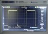
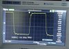
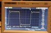
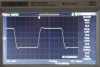
I have attached photos of the square wave performance at 1, 5 and 10 KHz and assumed that any further fine tuning would follow the re-installation of a step filter.

This where I am becoming confused - I assumed the role of the step filter was to limit the high frequency response outside the audible area because the frequency response being only 3dB down at 100KHz is excessive!

To start with I just installed the original components for the filter, C1 47pF and R3 4.7K, two issues immediately arose:
  • The high frequency response increased and a resonant peak appeared at around 80KHz (+0.8dB relative to no filter)
  • To my untutored eye the 10KHz square wave had deteriorated
I have stopped at this stage as I don't know quite what combinations I should try for the step filter. Should I just increase the value of the capacitor to get an actual reduction in high frequency response? Do I even need a step filter? I feel that I should be limiting the high frequency response in some way....

Any advice would be appreciated

Cheers, Malcolm
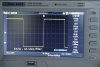
1KHzsquare-nostep.jpg 5KHzsquare-nostep.jpg 10KHzsquare-nostep.jpg 10KHzSquareplus-Step.jpg
 
The aspect of the step filter to appreciate is that it makes the phase worse around the middle of the step span, and so needs to be used such that the phase bump due to the step has subsided back to near zero change by the time the amplifiers 0dB crossing occurs. It is likely that the step filter in your amp is still causing significant phase shift at circa 80kHz, and that has reduced the phase margin so much as to allow oscillation - rather than actually helping. Removing the step filter removes any of that phase shift, and so seems to improve the phase margin back to a reasonable level. The other option is to reduce the degree of the step, such as raising the 4k7 to 10k or higher - Learned 1944 and Roddam 1951 are good references. It may be that your OT is good enough to not benefit from a step filter - the step filter can be used as a sort of a fix for not so good output transformers (as per the Williamson, where the step filter was only added under sufferance).

https://dalmura.com.au/static/corrective networks.pdf

https://www.americanradiohistory.com/Archive-Wireless-World/50s/Wireless-World-1951-03.pdf
 
If it doesn't have any nasty rising response without the network, I'd agree that it just may not be needed. Having wide response isn't necessarily a huge problem, the issue is that many transformers introduce phase shift at frequencies beyond 20kc, which turns the amp into an unstable mess of an oscillator. If it doesn't do this, you can ditch the network or just make it nice and gradual. The larger the value of the cap in the network, the lower the frequency it begins rolling off. The smaller the resistor, the more it drops things off.
 
and it does do that, but its also a low pass filter. All filters introduce some degree of phase shift though. If you mix and match it right, you can have a network that counters the phase shift introduced in the transformer. Of course if there is no signal at that frequency, there isn't anything to shift.
 
depends how you want to look at it. It passes highs to ground, or it allows lows to pass through the amp unaffected. I'd call it a low pass because the signal through the amp is what we're concerned with, and the filter is just disposing of signal we don't want.
 
if I didn't drop a decimal somewhere the -3db point of that network should be about 73khz, not factoring in any tolerances or extra ESR from the filter cap. You'd be at -45 degrees shift at that point.
 
Well, I am pleased to report that I seem to have a good result.....

After considerable experimentation I have ended up with an anode step network comprising a 10K ohm resistor and a 220pF capacitor and the global feedback loop comprises a 6K ohm resistor and a 390pF capacitor - negative feedback is 27dB.

The result is a flat frequency response from 10Hz to 20KHz with a steady taper to the -3dB point at 60KHz. There are no peaks in response all the way out to 200KHz. The square wave at 10KHz exhibits one small overshoot peak with complete suppression - no ringing is evident.

Thank you to all who have advised me on this - much appreciated....

Cheers, Malcolm
 
Sounds like the iron is indeed very good if it behaves that well at high frequencies. Good deal.
 
Are you able to test below 10Hz to check if there is a bump ?

I have recorded below 10Hz - down to 6Hz the sine wave remains intact and shows a roll off. From 5Hz down the waveform is "jumbled" and looks like a mangled square wave although the average Vrms still shows a steady roll off. I think I need to force the roll off from 20Hz to get rid of the junk waveform!

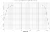
I have attached the 1 watt frequency response curve with an 8 ohm resistive load.

Cheers, Malcolm

Frequency Response Mon1.jpg
 
Malcolm, how are you acquiring your results ?

I have a hard time trying to make that low a measurement - my meters are only speced down to 10-20Hz, so I use a scope with dc response, otherwise I'd have to use a low frequency oscillator to provide a hopefully known magnitude from which to confirm what I think my soundcard is generating and measuring below 10Hz.
 
Malcolm, how are you acquiring your results ?

I have a hard time trying to make that low a measurement - my meters are only speced down to 10-20Hz, so I use a scope with dc response, otherwise I'd have to use a low frequency oscillator to provide a hopefully known magnitude from which to confirm what I think my soundcard is generating and measuring below 10Hz.

I am using a Vellerman HPG1 Handheld Pocket generator and a Siglent SDS 1072 CML Digital storage Oscilloscope. When the generator is connected directly to the oscilloscope I can display and measure a smooth sine wave response down to 1Hz. The generator can be stepped in 1Hz steps. As mentioned previously all was good through the amplifier until I got down to 5Hz when the waveform distorted beyong recognition! I guess this could be saturation of the tranformer core (?) as it is only speccied down to 10Hz at 1watt. I am thinking I will incorporate a high pass filter to get the amplifier frequency response to roll off from 30Hz.

For quicker results from 20Hz to 20KHz I use TrueRTA software but this cannot be used when looking at very high and low frequencies
 
if it runs down to 5hz before saturation, you've got very good iron. I expect at higher power output you'll see that saturation point move upwards. See what you get 1db down from full power output on both ends. That will be your power bandwidth.
 
That HPG1 looks like a neat device.

I found there was some benefit in being able to vary frequency in a continuous manner at below 10Hz, rather than in 1Hz steps, especially if there is a hump in the amp magnitude response due to a OT resonance, as it showed the build up and decay in magnitude as the driving frequency slowly moved through the resonance region. When there is a hump, the OT winding inductance varies with signal level, so the resonance frequency shifts about. Are you able to lower the output level to check output waveform change, and use XY observation of the distortion/waveform shape morphing?
 
if it runs down to 5hz before saturation, you've got very good iron. I expect at higher power output you'll see that saturation point move upwards. See what you get 1db down from full power output on both ends. That will be your power bandwidth.

As best I can see the -1dB points at 22 watts are around 20Hz (no high pass filter) and 20Khz although at 20Khz the sine wave is becoming slightly triangular (?) I have to take these readings fairly quickly as my load resistors (heatsinked) are only rated at 20 watts.

I am currently experimenting with a series capacitor at the input to act as high pass filter with a cut off around 15 - 20Hz.

Cheers, Malcolm
 
That HPG1 looks like a neat device.

I found there was some benefit in being able to vary frequency in a continuous manner at below 10Hz, rather than in 1Hz steps, especially if there is a hump in the amp magnitude response due to a OT resonance, as it showed the build up and decay in magnitude as the driving frequency slowly moved through the resonance region. When there is a hump, the OT winding inductance varies with signal level, so the resonance frequency shifts about. Are you able to lower the output level to check output waveform change, and use XY observation of the distortion/waveform shape morphing?

At 0.1 watt output the waveform did not distort from 10Hz down to 1Hz - there was no evidence of a peak. At 22 watts the waveform starts to distort from 17Hz downwards. Mullard recommend:

The prototype amplifier is capable of handling powers of at least 20W at frequencies as low as 30c/s without excessive distortion, but for very low frequencies it is desirable that the signal should be attenuated in the associated preamplifier.


I am not planning to use a preamplifier as such so I am looking at a high pass passive filter on the input.
 
FINAL UPDATE.....
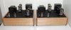
The second of the two monoblocs is now completed and the performance is well matched. Thanks again to all who assisted me in this - now to listen and enjoy!

Finished-Amps.jpg Frequency Response.gif Square Wave Final.jpg
 
Very nice! To be clear, the high-pass filter is in series with the input stage grid?

Correct - the 15nF capacitor is in series with the grid of V1. In conjunction with the 1M ohm grid resistor this gives a 6dB/octave roll off with the -3dB point at 10Hz
 
Back
Top Bottom