• The move to the new server is done. There are some software and database maintenance updates in process. This has us passing the hat around to help out. We appreciate any donations. Seriously, even a dollar helps. The payment page may be found here - https://www.audiokarma.org/support.html

MVP851 stuck in standby

Rob Warren

New Member
I’ve been looking to upgrade my CD player for a while now (Denon 5-disc from 1994), and came across a McIntosh MVP851 for a good price. I decided to pull the trigger, knowing it was not working properly. I like to “tinker” (as my wife calls it) with audio gear. I have a decent amount of experience troubleshooting and repairing tube gear, but not much with more modern equipment.
The CD/DVD player is stuck on standby mode. I found some threads about other McIntosh models and how to fix similar issues, but none work. I reached out to McIntosh and they sent the manual and schematics (awesome people), but did not discuss the issue. I’m hoping that someone in this forum may have solved a similar issue, and point me in the right direction. I’ve tested the transformer voltages, which checked out. I checked the function of the power relays, both of which worked properly when battery voltage applied. I have not done much more than that.
Any insight would be greatly appreciated.
 
Last edited:
Register to hide this ad
This is a pretty complex turn on. THere's a keep-alive power supply of 5V and 3.3V on the power supply board that provides power to the microprocessor on the display board, as well as a programmed chip of some sort on the power supply board (U6). U6 accepts the input from the power on pushbutton or the power trigger jack, sends a signal out to the microprocessor on the display board via the POWERTRIG line. The microprocessor then sets the POWEROUT line going back to the power supply board to +3V. The 3V then forward biases Q17 on the PS board, which turns on the relays.

First steps is to check the voltages I've circled in red on the PS board. THen see if you're getting 3V, after pushing the power button, at the green circled point. You could also try plugging a cable into the power trigger jack, it appears that it's triggered to on with a ground, so short the ends of the cable. Might need +12 to trigger, I'm not sure.

upload_2023-1-4_11-0-55.png
 
w3jn, I got at the machine tonight, and tested as you suggested. Voltages at the red circles (C28+, C29+, U7) all measures correct voltages. J5:11 however did not measure anything when I pushed the on button.
It took a few minutes to find all the right points…the board is set up in a logical way, but there’s not a lot of wiggle room. I’ll work on jumping J5:14 (pwrtrig) to ground and see what comes up.
While I was poking at J5, I noticed that pin5 was only reading 0.3V instead of 5V, but not sure if that’s relevant.
Thanks again for your help, it is greatly appreciated.
 
No, I meant the power trigger input jack in the rear of the unit - do NOT try grounding J5:14.

Check J3:16 for +3.3V, and J3:18 for +5 (this is on the display board)

Push the power button and check J5:6 and J5:7 for 3.6VAC between the two terminals - this is the filament for the VFD.

Put your VOM on J5:12. You should see +5 (or +3V). Push the power on - it should go to 0V when you do so. If not, the switch, or wiring in between is bad.

upload_2023-1-4_21-17-1.png
 
While you're in there, let's check the voltages at each pin of U6 on the power supply board. BE CAREFUL you don't short together two pins with your test prod.

Take voltage readings on all 20 pins (+ lead on the pins, - lead at ground point ie pin 2 or U5 or U7), then hold the standby button down (with your third hand lol) and read them all again. Report back, I'm wondering if it's getting VDD and also the state of pin 2, but we should do all the pins while we're there.
 
Awesome! It didn’t seem right to ground J5:14, which is partially why I didn’t do it last night.
This is incredibly helpful. Hopefully I’ll have some time tonight to dive in again. I’ll work on the third hand thing…I’ll try and recruit one of my teenage kids.
 
I’ve been looking to upgrade my CD player for a while now (Denon 5-disc from 1994), and came across a McIntosh MVP851 for a good price. I decided to pull the trigger, knowing it was not working properly. I like to “tinker” (as my wife calls it) with audio gear. I have a decent amount of experience troubleshooting and repairing tube gear, but not much with more modern equipment.
The CD/DVD player is stuck on standby mode. I found some threads about other McIntosh models and how to fix similar issues, but none work. I reached out to McIntosh and they sent the manual and schematics (awesome people), but did not discuss the issue. I’m hoping that someone in this forum may have solved a similar issue, and point me in the right direction. I’ve tested the transformer voltages, which checked out. I checked the function of the power relays, both of which worked properly when battery voltage applied. I have not done much more than that.
Any insight would be greatly appreciated.

Not sure if this will work on a MVP851, but did you try resetting the microprocessors by pushing and holding the on/off switch?
 
jayvis, I tried as many of these things as I could. there are a dozen or so variations of holding one or multiple buttons for given periods, holding while powering up, while powering down, etc.
I was really hopeful that it would be that easy.
Thanks for the suggestion,
Rob
 
jayvis, I tried as many of these things as I could. there are a dozen or so variations of holding one or multiple buttons for given periods, holding while powering up, while powering down, etc.
I was really hopeful that it would be that easy.
Thanks for the suggestion,
Rob

Noted. I found this in the owner's manual. Didn't realize it has separate on/off and standby switches. I assume that the unit has power when the on/off switch is turned on. Could there possibly be a disc that was left in or stuck in the drawer that triggered the unit to go into auto standby mode after 30 minutes? If so, try pushing the PLAY button to see if it turns back on.

Reset of Microprocessors
In the event the controls of the MVP851 stop functioning,
place the POWER Switch in the Off position for 1 minute,
then back On. This will reset the MVP851 microproces-
sors.
 
While you're in there, let's check the voltages at each pin of U6 on the power supply board. BE CAREFUL you don't short together two pins with your test prod.

Take voltage readings on all 20 pins (+ lead on the pins, - lead at ground point ie pin 2 or U5 or U7), then hold the standby button down (with your third hand lol) and read them all again. Report back, I'm wondering if it's getting VDD and also the state of pin 2, but we should do all the pins while we're there.

I tested all the points you suggested, and here’s what I found:
J3:16 = 3.3V
J3:18 = 5V
J5:6 to J5:7 = 0V
J5:12 goes from 5V to 0V when “on” pushed
Now on to U6, second number is with “on” pushed:
Pin 1: 5V, 5V
Pin 2: 5V, 0V
Pin 3: 5V, 5V
Pin 4: 2.5V, 2.5V
Pin 5: 2.3V, 2.3V
Pin 6: 0V, 0V
Pin 7: 0V, 0V
Pin 8: 5V, 5V
Pin 9: 5V, 5V
Pin 10: 5V, 5V
Pin 11: 5V, 5V
Pin 12: 5V, 5V
Pin 13: 5V, 5V
Pin 14: drifts from 0.01V to 4.4V. Bounces back and forth at many spots in between whether “on” is pushed or not. This one seems troubling.
Pin 15: 0V, 0V
Pin 16: 5V, 5V
Pin 17: 5V, 5V
Pin 18: 5V, 5V
Pin 19: 5V, 5V
Pin 20: 0V, 0V
I don’t like pin 14.
 
Noted. I found this in the owner's manual. Didn't realize it has separate on/off and standby switches. I assume that the unit has power when the on/off switch is turned on. Could there possibly be a disc that was left in or stuck in the drawer that triggered the unit to go into auto standby mode after 30 minutes? If so, try pushing the PLAY button to see if it turns back on.

Reset of Microprocessors
In the event the controls of the MVP851 stop functioning,
place the POWER Switch in the Off position for 1 minute,
then back On. This will reset the MVP851 microproces-
sors.

I tried these as well, but nothing. No disc, no Oreo cookies…nothing.
 
Pin 14 isn't connected to anything so lets not worry about that.

What we will worry about are pins 2, 9, 5 and 15. Pin 5 is supposed to be ground and pin 15 is the 5V supply for U6. You're seeing 2.3V and 0V respectively.... yet we're seeing 5V elsewhere. The 5V supply to U6, pin 15, is supplied by the same source that supplies the front panel microprocessor etc. Also we're seeing 5/0 on pin 2 but not pin 9. Something's weird and I think you might have figured the pin numbers wrong. Let's double check those voltages - and what does it do if you short the power trigger plug?

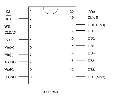
Below is the pin numbering scheme for a 20 pin DIP. This is some random chip but the numbering is the same. There might be a dot on one corner that would designate pin 1 instead of a notch.

ADC080X.gif
 
Pin 14 isn't connected to anything so lets not worry about that.

What we will worry about are pins 2, 9, 5 and 15. Pin 5 is supposed to be ground and pin 15 is the 5V supply for U6. You're seeing 2.3V and 0V respectively.... yet we're seeing 5V elsewhere. The 5V supply to U6, pin 15, is supplied by the same source that supplies the front panel microprocessor etc. Also we're seeing 5/0 on pin 2 but not pin 9. Something's weird and I think you might have figured the pin numbers wrong. Let's double check those voltages - and what does it do if you short the power trigger plug?

Below is the pin numbering scheme for a 20 pin DIP. This is some random chip but the numbering is the same. There might be a dot on one corner that would designate pin 1 instead of a notch.

ADC080X.gif
Makes sense…I had pin1 mixed up. There is a round indent at pin 1 that I did not see. I identified the real pin1, and here are the numbers:
Pin1: 5V, 5V
Pin2: 5V, 5V
Pin3: 5V, 5V
Pin4: 0V, 0V
Pin5: 0V, 0V
Pin6: 2.3V, 2.3V
Pin7: 2.5V, 2.5V
Pin8: 5V, 5V
Pin9: 5V, 0V
Pin10: 5V, 5V
Pin11: 0V, 0V
Pin12: 5V, 5V
Pin13: 5V, 5V
Pin14: 5V, 5V
Pin15: 5V, 5V
Pin16: 0V, 0V
Pin17: drifts all over the place, up and down from 0.001-4.4V
Pin18: 5V, 5V
Pin19: 5V, 5V
Pin20: 5V, 5V
I tried shorting the power trigger, and nothing happened. Did not try +12V to trigger. For this, should I use an external 12V source, or jump from the J12 ribbon? I’m nervous about jumping and potentially frying things.
So grateful for any advice you’re willing to share.
Rob
 
It appears Mac needs +5V for the trigger. You can get that from the PS someplace, but it seems that pin 17 on U6 is problematic. THat's an output from U6, which takes the power trigger from either the remote, from the standby button, or the power trigger jack and tells the microprocessor that power indeed has been triggered. It drives the base of Q3 on the display board; when it does so, Q3 saturates and drives the collector to ground. Take a voltage reading on the collector (pin 3) of Q3. Should be 5V. If it's not, there's a problem with that line - there are several pushbuttons, all with series resistors, that are on that line and the microprocessor decides which one is pushed by the voltage present on that line.

You could try shorting pins 1 and 3 (collector and emitter) of Q3 and see what happens. Might power up. Be careful when you do so that you don't short to other things.

Q3 could be bad, or U6 could be bad, or - depending on your voltage reading at the collector of Q6, another pushbutton in that series chain could be dragging down the voltage on that line.
 
It appears Mac needs +5V for the trigger. You can get that from the PS someplace, but it seems that pin 17 on U6 is problematic. THat's an output from U6, which takes the power trigger from either the remote, from the standby button, or the power trigger jack and tells the microprocessor that power indeed has been triggered. It drives the base of Q3 on the display board; when it does so, Q3 saturates and drives the collector to ground. Take a voltage reading on the collector (pin 3) of Q3. Should be 5V. If it's not, there's a problem with that line - there are several pushbuttons, all with series resistors, that are on that line and the microprocessor decides which one is pushed by the voltage present on that line.

You could try shorting pins 1 and 3 (collector and emitter) of Q3 and see what happens. Might power up. Be careful when you do so that you don't short to other things.

Q3 could be bad, or U6 could be bad, or - depending on your voltage reading at the collector of Q6, another pushbutton in that series chain could be dragging down the voltage on that line.

I probed around Q3, along with a pile of the other MPS 4124 transistors in that area of the board that are fed from the same board trace. Each measures 0.181V on the collector pin and 0.083V on base pin (traces for collectors and bases are connected by a resistor so this makes sense). Shorting pins 1 and 3 did not fire it up or allow me to do so. While in stby mode, are the collectors fed a reduced voltage (0.181V), or should they get the full 5V?
I believe I’m following your logic, Pin 17 of U6 feeds 5V to the PWRTRIG pin in J5. This voltage is all over the place. This is likely at least in part a cause of the issue at hand. If U6:pin17 is meant to provide 5V to pwrtrig, shouldn’t I be able to jump 5V to it and potentially turn things on by pushing the “on” button?
Either way, I have a part number for U6, and will see if I can get with the helpful folks at McIntosh to source a replacement…unless you think this is jumping the gun.
 
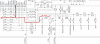
Let's not order U6 yet, because there oughta be 5V or so on pin 3 (collector) of Q3. Wondering if Q3 is shorted, or there's something else dragging down that line. On the display/keboard board check the voltage at both sides of R7 to ground. You should see 5V on both ends. If you see 5V on one end, and something less on the other, then we have an issue on that line in red that goes out to the open/close switch etc. If you're getting 5V on one end of R7 and something considerably less on the other, then check the voltage on both ends of R26. If it's zero or nearly so then Q3 is probably shorted.

upload_2023-1-8_9-32-3.png
 
To answer your other question, theoretically yes - if you put 5V on the powertrig line it should turn on Q3 regardless of whether you have the standby button pushed. It's not good to put 5V on the output of an IC however, so unless you disconnect just that powertrig line somehow I'd advise against doing that or it could damage U6.

If Q3 is shorted it could be dragging down the output of U6, hence the weird voltage at pin 17. And the fact that we're not seeing 5V at Q3 means there's something else going on in that circuit. THe microprocessor may not be expecting a ground at that line upon power up and is thus not recognizing the fact that Q3 is presenting ground - if in fact it is shorted.

U6 is a PIC of some sort but I can't find one that corresponds to the pinout on the schematic. Could have been a custom made PIC for McIntosh. If it is bad, hopefully they'll be able to supply one. If not we can do a workaround (wire the standby switch across the collector.emitter of Q3) but that will disable all the remote functionality.
 
Those KEYIN0, 1, 2 inputs to that microcontroller should be pulled up to 3.3VDC (NS3.3VD, at th VDD pin to the micro) b R5, 6, 7. The pushbuttons connect the circuit to ground. When a pushbutton is depressed, the KEYIN inputs get pulled down to a voltage the is the result of the voltage divider formed by the combination of R5, 6, or 7 and whichever series resistors are being shorted to ground by the pushbuttons depression. The micro senses and interprets the voltage at KEYIN to determine which key is depressed.

If no switches are depressed, the KEYIN voltages should all get pulled up to a solid 3.3V.

Q3 is an electrical "switch" that should only pull collector of Q3 to ground (~0.2V) like a pushbutton when the PWRTRIG signal is asserted to turn on Q3.

The STBY net s.b. pulled up to 5V b/c it's tied to the NS5V on the A/V/Psupply board. This pushbutton similarly grounds the STBY net when depressed, and should drive the U6 low when asserted.

That U6 device is I'm sure a custom programmed PAL that's interpreting all of this I/O and taking action on it.

U6 P2 0 and 1 are probably OK as you're measuring ~2.5V w/ the DMM. That's the clock for U6 so it should measure middle of the road w/ a DMM. Checking it w/ a scope would be better.

Is the PWROUT signal going high when the STBY PB is depressed?

That PWRTRIG signal at U6-17 wandering all over may be an issue. That should be set at one state or the other based on the logic of U6. It should probably be low by default based on the fact that R33 is trying to pull the net at Q3-2(base) down. That turns Q3 off so it's not pulling the KEYIN2 net down. PWRTRIG should only go high when driven high by U6. I'd definitely check Q3 to see if it's OK. KEYIN2 (and Q3-3) should rise to 3.3V when no key depressions or IR/Power control is trying to power the unit. If Q3 is OK, you might try isolating Q3 from PWRTRIG by pulling R35 just to see if Q3 shuts off properly (which should make Q3-3 rise to 3.3).

Fun stuff.
 
Silly questions - is your STBY LED lit when you apply power. And, when you try to power the unit, do you hear relays click but otherwise no display or other front panel indications? or do you hear nothing at all?
 
Silly questions - is your STBY LED lit when you apply power. And, when you try to power the unit, do you hear relays click but otherwise no display or other front panel indications? or do you hear nothing at all?

The Stby/on led turns on when I apply power. No power goes to the relays. I did confirm that the relays work by applying voltage. I confirmed the signal does get to the board when I push the power button.
 
Back
Top Bottom