• The move to the new server is done. There are some software and database maintenance updates in process. This has us passing the hat around to help out. We appreciate any donations. Seriously, even a dollar helps. The payment page may be found here - https://www.audiokarma.org/support.html

MX-1000 stopped working after I cleaned it!

Comment on the damage photo; OUCH! I agree that those boards are the prime suspect. I don’t know how the boards can get to that state without damage.

How about tracing the signal? Connect to the incoming signal to the boards using minigrabbers (not alligator clips) and see where the signal stops?

Nice work on the speaker connector replacement.
 
Last edited:
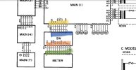
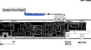
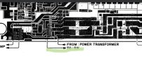
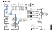
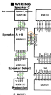
The signal to the meters comes from the protection board and routes to the meter board via the main and switch boards. Trace this route from the protection board back. Find out where you have signal.

9134091F-0B8A-45DB-B9B7-AB3C252DC8BF.jpeg
4CEF2FFF-C6F3-457D-B579-FB2A9DB42C50.jpeg
D47996AA-6BDC-4D71-A533-21326CB25CD5.jpeg
E5C72E95-C03F-4E03-B325-E92A353D15A2.jpeg
Use minigrabbers. Alligator clips are a blunt instrument that will get you in trouble.

EDIT: To be a little more complete, the signal to the C speaker board (Main 3) travels the farthest. If you track this signal from source (Main 1) to each destination (Meter and Main 3) you will find where the signal stops. This will provide a lot of good info for those experienced with this unit to help.

854B1399-EF40-4EAD-8203-92B5C105F835.jpeg

If you don’t have the service manual or schematic, you can get them from the AK Database.
 
Last edited:
Impact damage like that can flex the boards (all of them, actually) and crack both the board and individual solder joints. This will be worst around the screws holding the boards in place as they flex the most there under impact. A barely visible hairline crack can tear a trace and give you either intermittent or no contact.

Check them all, especially if something rigid or heavy is soldered on the board, the solder cracks in a nearly invisible ring around the lead or wire.

I've found ribbon cables with nearly all the connections simply floating in air too from solder failures.
 
Update, and thank you all for the help so far! This is a fun project and I'm learning so much!

I checked the protection board and the wiring going to relay circuit board. All clear! All good clean connections. Checked the protection circuit for any blown or open circuits. Also good.

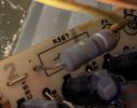
I then started to go through the relay circuit board and I THINK I found a resistor(?) that is blown? (Bad video linked) - it's R567? Could that be the source of my troubles?

IMG_8916.jpg
 
Update, and thank you all for the help so far! This is a fun project and I'm learning so much!

I checked the protection board and the wiring going to relay circuit board. All clear! All good clean connections. Checked the protection circuit for any blown or open circuits. Also good.

I then started to go through the relay circuit board and I THINK I found a resistor(?) that is blown? (Bad video linked) - it's R567? Could that be the source of my troubles?

View attachment 2964146
In fact, I think R564, 565, 566, 567 are all bad unless I'm using my multimeter wrong. R571 and 5572 both reading within range, but nada across the board for those other ones.


Screenshot 2023-08-20 at 4.26.55 PM.png
 
Those look like Metal Oxide resistors, hardly ever go bad … please double check the circuit traces. You can remove them from circuit and measure resistance to be sure.
 
Id do as sparkplug say's, lift one leg of each of those suspect resistors and then test.

Also is your DMM set to the correct resistor range? If it has AUTO range make sure you use that .
 
Hmm roger that! I've checked the ribbon cables to and from the relay circuit board and from the RCA jacks to the meter board, will start working my way back per Semanon's diagrams and your suggestions. Thanks all!
 
The signal to the meters comes from the protection board and routes to the meter board via the main and switch boards. Trace this route from the protection board back. Find out where you have signal.

View attachment 2963813
View attachment 2963814
View attachment 2963815
View attachment 2963816
Use minigrabbers. Alligator clips are a blunt instrument that will get you in trouble.

EDIT: To be a little more complete, the signal to the C speaker board (Main 3) travels the farthest. If you track this signal from source (Main 1) to each destination (Meter and Main 3) you will find where the signal stops. This will provide a lot of good info for those experienced with this unit to help.

View attachment 2963844

If you don’t have the service manual or schematic, you can get them from the AK Database.
Spent quite a bit of time tonight testing circuits / routes...I believe I may have found a couple bad ones?

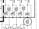
It looks like the orange wire (B+, not sure what that is an abbreviation for...) is a bad connection - tested from above and below - totally dead. The right channel is a little suspect as well, but I think it might just be a dirty connection on the top of MCB1 because when I test it from underneath RE/RO are clean.

Any thoughts? Thanks all!

Screenshot 2023-08-21 at 10.19.40 PM.png
 
Hi All,

I tried putting the crap back in, but no luck as of yet ;)

So, I realize I may not have been following your directions properly and I apologize for that - very new at this...and I definitely don't mean any disrespect as I'm basing everything and anything I'm doing off of your guidance.

The MX is idling a little low, but equal on both channels (8.5mV). The meter unit is working perfectly now - ran a test signal via RCAs. However, still no protection circuit light, no power light, no power to the relays, and subsequently no power to speakers bindings.

Connections between Main 1/2/3/4/7 are working normally. I've checked each joint on each ribbon several times for continuity and everything works. So I don't believe it's a loose connection.

Based on your advise I've checked M2 for any cracks or loose connections:
I've checked MB2 extensively over and over again, and have resoldered everything in case there were any hairline cracks on the solder joints I couldn't see under a magnifying glass.

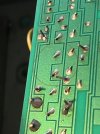
There is one potential crack in the board but coming from the earth/ground trace (grey wire from M1). Boosted the contrast to highlight. Let me know if this could be causing an issue?
IMG_8963.jpg

Based on your advise, I've traced the signal:
A 1khz signal is running from the RCAs normally up to R559, R560 on Main 2. I don't quite understand where I go from there...

I assume (and maybe I'm reading this incorrectly...) - that power to the diodes / lights on the protection board comes via B+ (working properly I think) through M2 (D531 is working) and through PO to M4, then to M7?

Anyway, I appreciate the help and feedback greatly!

 
However, still no protection circuit light, no power light, no power to the relays,
Check R549 .. It is a 1 Ω fusible resistor that supplies 30 vac to rectifier diode D525 -- which provides the DC to +B..

+B powers the red LED lights for protect and power indicators as well as the relay operating voltage.
B+, not sure what that is an abbreviation for...)
Is just a designator for a DC power supply voltage. Like +LB ,+ HB . +B2 etc.
 
Last edited:
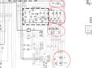
Adding to what was already clearly stated, check the voltages in the areas circled in red, if any not present or off, trace back its line to see where it starts deviating from normal …

6185603E-4457-4E87-A848-2950288CCDF2.png
 
I tried putting the crap back in, but no luck as of yet ;)

So, I realize I may not have been following your directions properly and I apologize for that - very new at this...and I definitely don't mean any disrespect
I meant no disrespect either, just for chuckles. My MX experience made me bitter, sorry.
 
Back
Top Bottom