• The move to the new server is done. There are some software and database maintenance updates in process. This has us passing the hat around to help out. We appreciate any donations. Seriously, even a dollar helps. The payment page may be found here - https://www.audiokarma.org/support.html

MX-1000 stopped working after I cleaned it!

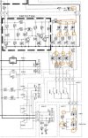
I'm reading 17VAC across R549. I am getting OL for resistance on it, but it's in circuit. Cosmetically it looks normal (I think). I assume that the only way to test R549 out of circuit will be to detach Subboard 2(?) to get access to the solder joints from underneath, right? If I'm understanding @avionic correctly, then it sounds like the resistance is too high, limiting the current getting through?

D525 + D528/D529/30/31 - I checked each diode to ensure it's functioning properly with the diode setting.

R564/5/6/7 all have normal resistance.

Hope I'm headed in the right direction! Thanks all.
 
I'm reading 17VAC across R549. I am getting OL for resistance on it, but it's in circuit.
What DC voltages (that 14.2 is not exactly DC, it’s half wave rectified, unsmoothed) are you measuring subsequent to R549 and D525 down the line? Do they more or less agree with the schematic?

In general, you shouldn’t measure resistors (or capacitors) in circuit because you are really measuring their equivalent resistance with whatever they’re in parallel with. If they’re in parallel with high resistance elements, then you might get something close to their true resistance, otherwise, your measurement could be way off.
 
Last edited:
I hope you’re making these measurements with your negative probe on the chassis ground and positive probe measuring two voltages across the resistor and then subtracting them. If the resistor is open, as it was suggested based on your description, then there’s something wrong since the ac voltage from the transformer is 30Vac and with an open resistor you should measure something around 30Vac (one end of the resistor being 30Vac and the other potentially zero). If you’re getting an actual voltage drop across the resistor, then it isn’t an open, current is flowing through it.

I‘m not sure how you’re making these measurements.
 
I hope you’re making these measurements with your negative probe on the chassis ground and positive probe measuring two voltages across the resistor and then subtracting them. If the resistor is open, as it was suggested based on your description, then there’s something wrong since the ac voltage from the transformer is 30Vac and with an open resistor you should measure something around 30Vac (one end of the resistor being 30Vac and the other potentially zero). If you’re getting an actual voltage drop across the resistor, then it isn’t an open, current is flowing through it.

I‘m not sure how you’re making these measurements.
Thank you, Sparkplug - I was taking the measurement wrong. Sorry! I feel like an idiot. Remeasured R549 and am getting 30Vac on one end and zero on the other. I haven't had a chance to get all the way down through the rest of the nodes yet. Hoping to get to it tonight.

Sounds bad to me.. Should have seen less than 1 Ω in circuit. A 1Ω resistor is basically a fuse..
The part # for this HV453100 I believe. If this part is indeed bad, I need to get a replace 1/4 w 1ohm fusible resistor?

Thank you both for the help.
 
Welp! Sorry about the lengthy pause, but I just finally had a chance to replace R549…AND IT WORKS!!! Protection circuit functioning normally. Crisp clean audio out of all three channels!

Thank you all so much. I could not have fixed this without your help and guidance. Literally the first time I’ve ever done anything with electronics other than fixing a lamp.

Just hooked it up to my Infinity RSIIBs and the sound is just…wow.

Thank you thank you thank you!
 
Welp! Sorry about the lengthy pause, but I just finally had a chance to replace R549…AND IT WORKS!!! Protection circuit functioning normally. Crisp clean audio out of all three channels!

Thank you all so much. I could not have fixed this without your help and guidance. Literally the first time I’ve ever done anything with electronics other than fixing a lamp.

Just hooked it up to my Infinity RSIIBs and the sound is just…wow.

Thank you thank you thank you!
:thumbsup::music:
 
Welp! Sorry about the lengthy pause, but I just finally had a chance to replace R549…AND IT WORKS!!! Protection circuit functioning normally. Crisp clean audio out of all three channels!

Thank you all so much. I could not have fixed this without your help and guidance. Literally the first time I’ve ever done anything with electronics other than fixing a lamp.

Just hooked it up to my Infinity RSIIBs and the sound is just…wow.

Thank you thank you thank you!
:rockon: I was no help but...congrats. Rock on
 
Hi All! Back for round two if anyone is willing to give me a little bit of advice. Unfortunately, the amp stopped working again this week. It seems to be the same issue as last time, powers on, but the protection mode light doesn't come on, and the relay doesn't click.

I've replaced R549 again, just to be sure, but still no luck. I'm getting proper readings prior to R549 at F503 (30.1AC) / F504 (30.2AC). However I'm getting -1.5DC at D525, D528, D531, D530, D529. I believe I am measuring it correctly, and have tested the measurements in other areas of the system and gotten correct readings to make sure it's not user error. So I assume my issue is at D525? I've tested the forward and reverse bias in diode test mode, and am getting a super low voltage reading in both directions about .01DC. I believe that means it's shorted, correct?

(Assuming I'm correct in isolating the issue) I'm not sure what part I should be replacing that rectifier diode with as it seems discontinued: https://www.datasheets360.com/part/detail/1sr35-100at-93x/1174338506996276741/

Thank you for the help!!
 
Please test for DC voltage at the speaker terminals 1st.
No speakers, no load, no input signal. Doesn't matter whether it's on the DBT or not. Let's make sure we're shooting the "right" side.
 
On the main board. Where the two amplifier assemblies are soldered. Each amplifier assembly has a connection marked ( OUT ). This is a good place to measure the DC offset.

Be careful not to short the " OUT "pin to any adjacent pins or you will burn up and the amplifier in a fraction of a second.


Mini grabbers recommended.
 
Thanks all. Will report back!

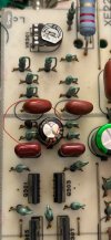
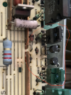
EDIT: Well, my day was going bad already, and then I did manage to burn out the left assembly. What an idiot I am - I thought I was being incredibly careful, but I guess not. I flamed out Q313, Q315 (maybe?), and one of the resistors that follows - haven't figured out which one yet - not labeled on the board so trying to figure out via the schematic. Guess I have to work on replacing those first now. Oof.

Or do I just throw in the towel?


IMG_1199.jpgtempImageVIOAqZ.png
 
Last edited:
Thanks all. Will report back!

EDIT: Well, my day was going bad already, and then I did manage to burn out the left assembly. What an idiot I am - I thought I was being incredibly careful, but I guess not. I flamed out Q313, Q315 (maybe?), and one of the resistors that follows - haven't figured out which one yet - not labeled on the board so trying to figure out via the schematic. Guess I have to work on replacing those first now. Oof.

Or do I just throw in the towel?


View attachment 3246341View attachment 3246352
Crap, and you did not have the camera ready for the 4th fireworks? Mine is always out of battery when this kind of crap happens :biggrin:
Well, a sign it needs to go to @avionic
 
Back
Top Bottom