• The move to the new server is done. There are some software and database maintenance updates in process. This has us passing the hat around to help out. We appreciate any donations. Seriously, even a dollar helps. The payment page may be found here - https://www.audiokarma.org/support.html

MX110 hum (continued)

jdkinase

New Member
Hi! Need some advice regarding my MX110 (s/n 591Z9), which was fully recapped in 2013 and partially last year with a transformer replacement. Last year, I had the unit serviced by a local McIntosh service center to fix a loud hum, wherein they added a 10 uF/450 capacitor (I assumed at the time that they'd just replaced a cap, not added a new one.) The unit seemed okay until recently, when it seemed to have developed a lot of static/hiss, so took it back in but they said it checked out okay when connected to my MC240. Within an hour of listening to it at home, significant hum came back, on all inputs except Tape Monitor, and which varied with volume.

The photo below shows
1. the 10 uF/450 capacitor added between C116 (CE Manufacturing from 2013 recap) and ground;
2. C115 appears to be leaking, looks original, I plan to replace it with a 4x50 uF

First, what purpose the 10 uF capacitor on C116 would serve? Is it a band-aid for a faulty section of the C116?? Should I just replace C116 when I replace C117?

Second, if I may, there is no resistor connected between the silicon rectifier and ground. I've seen different values listed in this forum, so, if it's needed, what value??

Many thanks in advance!
 

Attachments

  • C116-C117 issues.JPG
    C116-C117 issues.JPG
    175.1 KB · Views: 58
Register to hide this ad
Hi! Need some advice regarding my MX110 (s/n 591Z9), which was fully recapped in 2013 and partially last year with a transformer replacement. Last year, I had the unit serviced by a local McIntosh service center to fix a loud hum, wherein they added a 10 uF/450 capacitor (I assumed at the time that they'd just replaced a cap, not added a new one.) The unit seemed okay until recently, when it seemed to have developed a lot of static/hiss, so took it back in but they said it checked out okay when connected to my MC240. Within an hour of listening to it at home, significant hum came back, on all inputs except Tape Monitor, and which varied with volume.

The photo below shows
1. the 10 uF/450 capacitor added between C116 (CE Manufacturing from 2013 recap) and ground;
2. C115 appears to be leaking, looks original, I plan to replace it with a 4x50 uF

First, what purpose the 10 uF capacitor on C116 would serve? Is it a band-aid for a faulty section of the C116?? Should I just replace C116 when I replace C117?

Second, if I may, there is no resistor connected between the silicon rectifier and ground. I've seen different values listed in this forum, so, if it's needed, what value??

Many thanks in advance!
From the photo it looks like there are a few band-aids. This was done at a "local McIntosh service center"? Perhaps a better technician is needed?
 
Importantly, is it 60 hertz hum or 120 hertz? Very important that you specify as the two lead in completely different directions.

A 120 hertz hum indicates a power supply issue. A 60 hertz hum could be filament to cathode leakage, a ground loop, wire dress, loose ground, or many other things.

First, along with determining what frequency the hum is at, does it to it with no input connected? Tuner only? Phono only? All inputs?

I recently found an issue with mine when the stereo light wouldn’t go out. I found 106V on a spot that should have been ground potential in the stereo demodulator circuit. Long story short there’s a screw on the rear input terminal board whose threads were stripped and it was through that one screw that much of the input circuitry is grounded to the chassis. While I had no hum in that case it’s indicative of the issues you can find.
 
If I might also offer --

1. The large brown radial lead cap attached to C116 that you are indicating is a 10 uF cap looks by physical size to be very much bigger than 10 uF. Regardless however, it is a band-aid that never appeared in the original factory wiring. If C116 is good in all sections (which is the filter cap for the tuner circuits), then no such band-aid is needed for quiet operation. The brown radial cap shown added to C116 is the only band-aid appearing in your pic.

2. The blue axial lead cap attached to the silicon rectifier T-strip should in fact be a 10 uF cap. The one installed is obviously a replacement cap for the original, which is designated as C114 on the Z schematic. Confusion arrises from the fact that the M version of the MX-110 did not have a discrete cap in this location, so those more familiar with the M version might initially view such a cap in the Z version as an aftermarket modification -- particularly if it is a modern replacement cap as shown in your pic. In fact, its inclusion was part of the significant power supply upgrades made by Mac when the Z version was developed.

3. The other modern discrete cap shown bent down behind the rear red PEC should be a 12 uF (or larger) cap, incorrectly labeled on the Z schematic as simply C115. Now obviously being a discrete component, it can't be part of the C115 can cap sections, so the schematic mislabeling causes confusion. As installed at the factory, the real C115 is in fact a four section cap, but has two of its sections paralleded. The two paralleled sections together make up the single 70 uF cap shown on the Z schematic as C115C, which further adds to the confusion when trying to match the schematic to the build. Finally, the highest numeric label for capacitors I could find on the Z schematic is C124. But -- as another schematic error -- there are two separate (unrelated) caps labeled as C124 on that schematic, so for at least my own purposes, I have labeled the original "C115" 12 uF cap as C126.

4. The design of the 110's HV power supply employs a CT winding in the power transformer, allowing for "full" and "half" voltage supply points. But the load attached to these points is wildly different, with far greater current flow being drawn at the half voltage supply point than at the full supply point. As a result, it is impossible to use a single resistor in the negative lead of the bridge rectifier array to compensate for the increased efficiency of the silicon versus the original selenium. A given resistance value can make one voltage tap correct, or the other, but not both. Therefore, two resistors must be used to correctly compensate the unit when silicon replacements are installed -- one between the positive lead of the bridge and C114, and one between the transformer HV winding CT and C116A. In a correctly operating Z, a 560Ω 2W resistor at the bridge location, and a 100Ω 5W resistor at the HV CT lead will produce normal voltage levels in the Z. The negative lead of the bridge should be grounded as in the original design.

5. Your unit also shows more evidence of a significant factory wiring lead placement error I discovered through troubleshooting a client's MX-110Z hum complaint, that had symptoms nearly identical to those you describe in your unit. Apparently Mac ultimately became aware of the problem as well as once I had determined what the problem actually was, continued research (by others) then showed (through underside pic observations only) that the factory had resolved the problem in later Z units with a change in lead placement that was in a manner very similar to the one I had published here. Either way works equally well, but nobody knew about the change Mac made to correct the problem because they never offered their fix in a service bulletin -- I guess because it technically didn't represent a circuit change. The cause therefore had to be sussed out independently. In any event, with no published correction from the factory, the run of units affected never had a chance to be corrected in the field -- all the owners of those units knew is that their unit hummed. The reduction in hum made by the fix proposed is significant -- you can find the thead I published on it here:


I hope this helps!

Dave
 
Those caps underneath which are wired in parallel with a section of the electrolytic can cap, are your band aids. They were installed by a cheap or incompetent tech who probably has no business inside a McIntosh. My Mx110 had this type of recap done to it and it also hummed. I made an order with hayseed hamfest and they got me squared away with brand new electrolytic cans. That's what yours will need before any other work occurs. New cans, put wiring back to factory, then fix whatever you find wrong, if anything...
Then enjoy it. It's real hifi gear.
 
Many thanks for the responses! I should mention that the 2013 re-cap was done by Terry Dewick, with subsequent work on power supply done by me when the transformer went out last year. I inherited this MX110 and MC240 from my dad, so grew up listening to rock-and-roll (and his opera, indirectly) through the 60's-70's; it's an heirloom, though not sure my sons will want tube equipment (did I raise them wrong?!).
Anyway, apologies for not providing more information, I will try to address here.
@w3jn
- Hum is predominantly 120Hz; no inputs; selector at tuner, aux, phono but NOT when tape monitor is active. Increases with volume control. I confirmed as much as possible it's not a local ground loop;
- I also noticed the stereo light doesn’t go out (tech missed that one too!), visually that board looks OK but I'll put that on the to-do list;
@dcgillespie
- My bad, the large brown cap at C116 is 470 uF/200V;
- I replaced the 10 uF/450V C114 when I replaced the transformer, along with new diodes, hence my questions about the resistors there as they were not present when I got in there. Would possible over-voltage there have caused failure of C115 or C116??
- I read your input on re-routing the output cable, quite interesting. Will put that on the to-do list.
 
If 120 Hz it's either a PS issue or the issue Dave noted above. Given that it's affected by the tape monitor, and Dave's mod involves the tape mon switch, I'd follow Dave's excellent analysis first.

There is a pot on the top of the chassis to adjust the stereo light. However, even after I fixed the bad ground screw, the light didn't work right (and FM stereo was poor) until I completely aligned the FM, including the stereo demultiplexer subchassis.
 
As to the unit as shown, I would again respectfully suggest that there is only one “band-aid” cap shown in the underside pic of your MX110Z. The other two modern discrete electrolytic caps visible in the pic are replacing original discrete electrolytic caps factory installed at those locations.

To be honest, I've never seen any MX-110s that were (previously) converted to silicon that was done so properly by adding the two resistors I mention. Either no resistors were added, or sometimes just one is added in the negative bridge lead, which is always either not very effective at best, or causes other problems worst case. It's certainly possible that not including any resistance would stress the original can caps, but by this time, they should be replaced anyway.

Dave
 
As to the unit as shown, I would again respectfully suggest that there is only one “band-aid” cap shown in the underside pic of your MX110Z. The other two modern discrete electrolytic caps visible in the pic are replacing original discrete electrolytic caps factory installed at those locations.

To be honest, I've never seen any MX-110s that were (previously) converted to silicon that was done so properly by adding the two resistors I mention. Either no resistors were added, or sometimes just one is added in the negative bridge lead, which is always either not very effective at best, or causes other problems worst case. It's certainly possible that not including any resistance would stress the original can caps, but by this time, they should be replaced anyway.

Dave
Received parts and proceeding with replacing the cans. A couple of clarifications:
- I'm using a 4x50uF can at C115 as noted in previous posts. Are the two 50 uF leads to be jumped as originally wired, increasing C115C to 100uF, or use only one 50uF lead as C115C?
- Clarifying "one [resistor] between the transformer HV winding CT and C116A", is there a schematic or photo showing the resistor(s) added?
 
Jump the two cap sections together as before. When I get home later on tonight, I’ll see if I’ve got any pics of my own work in the power supply area. Otherwise, the new resistors are added between the positive output of the new silicon bridge and the components originally connected to the output of the old selenium bridge, and between the HV winding CT lead, and the components it originally connected to.

Dave
 
Jump the two cap sections together as before. When I get home later on tonight, I’ll see if I’ve got any pics of my own work in the power supply area. Otherwise, the new resistors are added between the positive output of the new silicon bridge and the components originally connected to the output of the old selenium bridge, and between the HV winding CT lead, and the components it originally connected to.

Dave

Hi Dave,

I only added one resistor. Do you have a photo of the recommended approach with the second resistor installed? Thanks!


mx110.jpg
 
Hi Monk -- I'm sorry I never posted any pics earlier -- just too much going on!

Here are three pics that might help. This is a client's piece that had previously been serviced before being sent here, arriving with a variety of issues to be addressed (FM issues, hum, and incomplete recap among others). Besides resolving those issues however and relevant to this conversation, one of the other requests was to change the selenium rectifiers that remained in the unit to silicon. In doing that however, the expected over-voltage jump that should have been produced when the silicon was installed never occurred. The voltages simply became normal with no compensation installed at all. When it arrived here, the B+ voltages were somewhat lower than normal, but nothing out of the ordinary that would have been produced by sagging selenium. So nothing was thought to be of concern until the silicon was installed, and the results were not as expected. This lead to the finding that the unit was actually only operating on 1/2 of the HV secondary -- the other half had simply gone open. So besides the other issues, the power transformer had also failed, but in such a way that the client never knew it because the unit still operated with all outward appearances of normalcy, albeit with the original issues providing the reasons that it had been sent in the first place. In a round about way then, this is all to say that the pics of the work provided are based on the installation of a new power transformer as well. The modification with the two resistors would be the same in either case, and the new power transformer installed is an excellent replacement piece, but the values when using an original good power transformer may be slightly different.

I hope this helps!

Dave


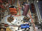
Below: A closeup of the work. The 680Ω 2W resistor is connected between the + output of the bridge, and C114. The 100Ω 5W resistor is connected between the HV winding CT lead, and C116A. All voltages in both the tuner and audio sections are completely normal with these modifications in this unit with the replacement transformer installed:
SAM_3736.jpeg

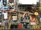
Below: A wider angle shot of the area:
SAM_3735.jpeg

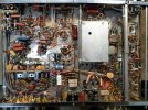
A shot of the completed work after all work was finished:
SAM_3737.jpeg
 
I’m going to step in here and say a big thanks to Dave as well. I did the single resistor mod to drop the voltages down and was not particularly happy with the results. My MX110 came to me with a bridge rectifier installed, but nothing to compensate for the resulting higher voltages. I’ll be making the two resistor mod soon!
 
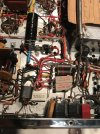
I did Dave’s 2 resistor circuit by adding two small terminal strips. It put the voltages right on. Thanks Dave!
 

Attachments

  • E094FEA7-2EA4-48C9-BC4E-3869686BA652.jpeg
    E094FEA7-2EA4-48C9-BC4E-3869686BA652.jpeg
    164.1 KB · Views: 27
The down side of using a single resistor -- besides never being able to produce the correct operating voltages throughout the unit -- is a matter of the poor regulation it produces. It works in a kinda-sorta way, but does not deliver the performance that Mac intended of the original power supply.

The B+ power supply in the MX110 is effectively two (aprox) 130 vdc power supplies stacked on top of each other (effectively in a series aiding configuration). The bottom end of this series connection is the negative side of the "bottom" supply, and is connected to ground. The point between the two supplies (located at the PT's HV winding CT lead) is the + output of the bottom supply, producing an output of ~ 130 vdc, and is used to power all of the tuner and MPX circuits throughout the unit. The HV winding CT lead also represents the negative side of the "upper" supply, with the + output of this supply (now 260 vdc above ground) powering all of the audio circuits. This is a very effective way of providing significantly different power supply points for equipment having such needs, and was used by other manufacturers as well of that day -- Fisher being the most notable.

The beauty of the connection is that it provides two low impedance outputs to the two different circuits it powers, which means it provides very good regulation in the face of any varying current demands from either of the two circuits being powered. The filtering circuits notwithstanding, the regulation of the basic supply is the product of that which the power transformer and the selenium rectifiers can provide. Since they are both low impedance devices, the regulation is therefore very good.

The problem that comes in is the fact that the current draw from the tuner section can vary wildly from a no reception condition (very high current draw), to a tuned condition on a strong signal (nearly half of the former current draw). For a low impedance power supply, it takes such changes in current draw in stride, affecting it relatively very little. And that's a good thing because whatever the voltage produced by the bottom supply is passed right on up the chain to the upper supply that powers the audio circuits. By comparison, the current draw by the audio circuits is absolutely dead steady, regardless of signal conditions in the audio circuits. No signal, max output, any input, it doesn't matter -- the current draw is the same at all times, and also just a fraction of the current drawn by the tuner circuits.

Silicon rectifiers are much lower impedance devices than the older selenium devices are. That's why when they are installed to replace older selenium devices, all the operating voltages are increased. This also greatly increases the peak current demands drawn from the HV winding in the power transformer, and increases its heating -- this in a transformer that has already shown it is not the most durable transformer ever made (produced externally for Mac). So adjustment is highly recommended when silicon is installed in place of the original selenium in an MX110.

Now if you simply place a single resistor between the negative output of the bottom supply and ground in an attempt to adjust both of their outputs, that approach can never adjust the output of both supplies properly, because that approach could only do so if the current draw from both supplies -- relative to ground -- is exactly equal -- which it never can be in this case because the bottom supply is actually powering both the tuner and audio circuits (since they both reference ground), while the upper supply is powering just the audio circuits. Also, if such an approach is attempted, which circuits are you trying to make right -- the tuner circuits or the audio circuits? You can't make both right, and even if you compromise with the value of a single resistor to try and make both close, you end up increasing the impedance of the overall supply, so that now changes in current draw in the tuner section will have a significant impact on not only its operating voltages, but also those in the audio circuits as well. I'm not sure where the idea of using a single resistor for compensation ever came from, but I surely doubt it's anything that Mac would have done had they ever changed over to silicon during production of this model.

By leaving the negative lead of the bottom power supply grounded, and then adjusting the positive output of each supply independently of each other (using its own resistor) according to its own load demands, then the overall impedance of both supplies remains unchanged with the new silicon devices, and power supply performance of the original design both in terms of output voltage and peak current draw from the power transformer is closely mimicked. Do the new resistors add any impedance to the power supply? Nope. They are simply replacing the effective impedance presented by the original selenium devices (when good) to the loads they powered. It is important to remember that when installing such resistors, they are to be placed between the raw output of these supplies, and the first filter cap they serve. That way, the value of the resistors becomes the effective resistance of the old selenium devices, and in doing so then maintains the original peak current draw levels from the power transformer.

I hope this helps!

Dave
 
Back
Top Bottom