• The move to the new server is done. There are some software and database maintenance updates in process. This has us passing the hat around to help out. We appreciate any donations. Seriously, even a dollar helps. The payment page may be found here - https://www.audiokarma.org/support.html

My Denon DRM-550 does everything, except play.

Frank Wild

New Member
I recently won a Denon DRM-550 at auction. I have had one of these in my “not for sale” collection for fifteen years and it’s been mostly great. Now I have two, but there’s a problem with the second one. Mechanically, it's is tip-top. FF and RW are solid. The meters all work as they should. I can even record, but I have to use another deck to verify the recording because this Denon is silent in PLAY mode. Everything turns and the tape is in place, but there’s no signal and no meters.

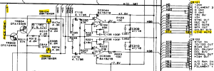
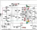
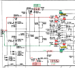
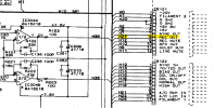
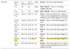
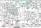
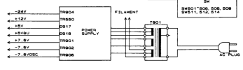
The image is from the schematic. I’m able to verify the voltages given here with one exception: TR904 isn’t accessible until I pull the PCB out, which I’d rather avoid. I have fixed over a dozen decks since I started doing this, but mostly mechanical issues. I need a little help from my friends. I have the rare option of comparing this unit to my working one, but I don’t know how to proceed. Ideas? I do have the service manual and a multimeter of course.
 

Attachments

  • Screen Shot 2024-08-19 at 4.21.37 PM.png
    Screen Shot 2024-08-19 at 4.21.37 PM.png
    62.3 KB · Views: 8
Register to hide this ad
One more question: when you are recording... and the meters move, can you monitor and hear the audio on the outputs or headphone jack?
 
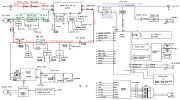
OK, so here is the block diagram of the DRM-550. I have marked the signal paths red for recording, green for playback, and blue for output.
  • Since apparently you can record OK, the red path from Line In, through the Dolby chip to record out and IC301 to the R/P head seems to function.
  • Also, since you can monitor the recording using headphones, the blue path works.
  • The VU meters also work during recording, blue path, so the signal is getting through IC305 OK.
  • It is the green path from the R/P head, through switch TR101/201, IC302, RT101/102 into the Dolby IC that is problematic.
1724305000060.png
 
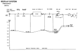
Here is a signal flow diagram of the Playback.
1724305234021.png
Here is the same diagram for REC-PLAY.
One thing to note is that the Line Mute switch does not appear in the circuit (as least the simplified circuit). Maybe it is always muting the audio on Playback?

1724305301334.png
 
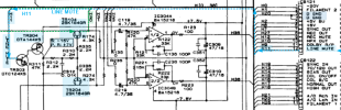
Here is the circuit for the Line Mute signal.
See if you can find header CB121, Pin 12 and check to see if Line Mute is high or low, or if it changes when you hit PLAY.
Line Mute is an inverted signal, so probably = Low when muted, High when unmuted.
1724305836984.png

1724306186497.png
 
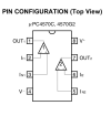
This is terrific! I appreciate the if/then logic that led you to this conclusion. In my own half-blind way, I have fumbling toward the same one. My suspicion is that IC302 may have failed. Yesterday I took voltage readings from ground to the 8 pins on that op amp, both on my working unit and the dead one. I got a big surprise. Here is the pinout for C4570:
pinout diagram µPC4570C.png
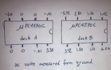
And here's what I measured:
IMG_0100.jpg

What was my surprise? Well, A is the working unit and B is the bad one! I'm mystified. I've double and triple-checked these results.
I hope this makes sense to someone who understands circuits better than I do.

What is "line mute"? Is its purpose to block the signal from the play head anytime I'm not in playback mode?
I think if TR104 or TR204 failed, I would still have a signal on one side, no?

THANK YOU!
 
The voltages that you measured looked different, but I'm not sure it's the chip?
Could you please measure the voltages highlighted in red on the schematic for TR302, both sides of R348, both sides of Zener ZD301 and see if they match the schematic for REC & PLAY?

My reasoning for thinking it's not the OP amp is because if you take the + & - inputs, it looks like it's doing what it should +2.80v -1.16 = 1.2v and you are getting 1.02v at the output. The DC supply voltages look OK (pin 6 & 4).

1724513834134.png
 
Last edited:
> Could you please measure the voltages highlighted in red on the schematic for TR302, both sides of R348, both sides of Zener ZD301 and see if they match the schematic for REC & PLAY?
Measuring VDC from ground...
At the REC OUT notation next to the diode ZD301: play -0.4, record 5.25 (Play voltage should be -3.3) (That's the same as one side of R348)
At the opposite side of that same diode: play 4.39, record 7.39
At the opposite side of R348 (schematic says -7.5), -7.39
At the emitter of TR302: play 7.07, record 7.40
At the base of TR302: 5.76

With gratitude.
 
Last edited:
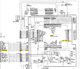
Thanks. I updated the schematic and traced the REC OUT signal back to its source.
1724598451821.png

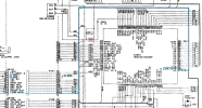
REC OUT is labeled H27, follow it and it routes to connector CB121 pin 8.
1724598476791.png

Now, CB121 pin 8 connects to W121 pin 9, which ends up on IC501 pin 49 REC OUT.
1724598494409.png

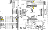
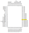
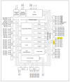
IC501 is a micro controller (AFAIK). Pin 49 is highlighted below and is a programmable I/O pin for the microcontroller.
1724599188182.png 1724599368607.png
1724599524248.png
Sorry for all of this detail, but I thought that I would capture it for any future reference.
If this chip is bad, probably impossible to replace since it has programming stored in the ROM.
Can you check the Zener diode, ZD301, to see if it's bad. Maybe you can lift the end that connects to R348 then re-check the voltage at R348 in REC and PLAY again.
Thanks.
 
Sorry to take so long. I got busy with auto repair, more urgent.
>Can you check the Zener diode, ZD301, to see if it's bad. Maybe you can lift the end that connects to R348 then re-check the voltage at R348 in REC and PLAY again.

I finally figured out how to get access to the solder side of the circuit board and I will get those measurements real soon.
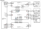
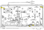
Meanwhile, I noticed that the "ground" on the audio PCB is not continuous with the ground on the power PCB. Or at least, that's true when the cover is off. Near the rear RCA jacks, capacitor C390 is "grounded" through a wire that, if the cover is off, connects to nothing. On page 21 of the manual, see W001 and W005. From the start, I have been measuring voltages from the ground of the power board instead (W005). And I think that was the right decision. I'm just surprised that they counted on the cover screws to assure continuity between them. In fact I'm almost shocked :) Please stay tuned for new voltage readings with one end of ZD301 lifted out of the circuit.
 
Meanwhile, I noticed that the "ground" on the audio PCB is not continuous with the ground on the power PCB.
If you examine the block diagram and board interconnect, you will notice that there are three types of "Grounds". Separating grounds is usually done to reduce digital noise on the analog signals.
  1. GND (Assuming chassis ground)
  2. D GND (Digital Ground)
  3. A GND (Analog Ground)
1724823456941.png
Also looks like each board has a wire to connect to chassis.
1724824163285.png
 
Last edited:
There is a signal "LINE MUTE" that gates the audio signal ON/OFF going to the output. The signal is gated by FETs TR104 & TR204.
The mute gating signal is on the TR304 collector. It should be:
  • STOP = -16v
  • PLAY/REC = +7v
1724867925827.png
The LINE MUTE signal looks like it is generated in IC501 pin 26.
1724868014977.png

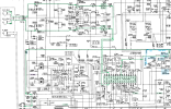
The audio signal from the PLAY HEAD follows the green dotted line path to the output jacks. So, if the PLAY signal from the tape head is not getting to the output jacks, the problem has to be a component in this green line path. And, since you have the problem in both channels, it is something that is common to both L & R channels.
1724868415527.png

Sorry, one more path to check R/P (see purple arrow). Measure voltage in record and play. thanks.
1724882722772.png
 
Last edited:
Okay, with the anode side of ZD301 out of circuit, I get, at R348: play -1.42v (was -0.4, should be -3.3), record 5.25 (unchanged).
I checked ZD301 with the diode checker and it looks okay: .743 in one direction, ∞ in the other.
With ZD301 disconnected, there's a hum in the headphones in play mode which is loud enough to show easily on the meters.

Other measurements with ZD301 pulled on one side:
TR302 base in play now 7.30 (was 5.76).
The disconnected side of R400 is now 7.32 in play (was 4.39). Record voltage now 7.35 (was 7.39).

There is a signal "LINE MUTE" that gates the audio signal ON/OFF going to the output. The signal is gated by FETs TR104 & TR204.
The mute gating signal is on the TR304 collector. It should be:
  • STOP = -16v
  • PLAY/REC = +7v
View attachment 3284344
The LINE MUTE signal looks like it is generated in IC501 pin 26.
View attachment 3284345

The audio signal from the PLAY HEAD follows the green dotted line path to the output jacks. So, if the PLAY signal from the tape head is not getting to the output jacks, the problem has to be a component in this green line path. And, since you have the problem in both channels, it is something that is common to both L & R channels.
View attachment 3284348

Sorry, one more path to check R/P (see purple arrow). Measure voltage in record and play. thanks.
View attachment 3284512
At the purple arrow, I get about what I should: REC -.35v / PLAY -7.4
Likewise at the collector of TR304: STOP -15.6v / PLAY-RECORD 7.3v
Should I pull ZD301 completely out and check its zener voltage? (It checks out fine with the diode tester: 0.743v/ OL.)
As expected, when I replaced it into the circuit, the loud hum and white noise disappeared again.
> it is something that is common to both L & R channels. Would C117 fit that description? Or IC303?
Or, is there any chance that TR104 and TR204 got damaged by the same incident, and thus don't gate the mute signal as they should? Seems pretty unlikely, right?
 
Last edited:
Should I pull ZD301 completely out and check its zener voltage?
You could test it in circuit by measuring the voltage across the Zener. According to the datasheet, it should zener at 5.2 to 5.5V.
I'm not sure how the Zener is used in this circuit. Usually when the voltage across the Zener is > the Zener voltage, then it will conduct in the reverse direction.
In this case:
Record: Anode voltage = 5.3v, so the voltage on the cathode would need to be > 5.3v + 5.2v = 10.5v to start to Zener?​
Play: Anode voltage = -3.3v, so the cathode voltage would need to be -3.3v +5.2v = 1.9v to start to Zener.​
Neither seem to be what we have going.​
TR302 is a strange transistor symbol. Apparently, it has internal biasing resistors.​
I don't understand the voltages at ZD301 and TR302. Can you check the R/P voltages on the emitter, collector and base of TR302 in Rec and Play?
Is there a chance that TR104 and TR204 got damaged by the same incident, and thus don't gate the mute signal as they should?
I don't know. If you had a scope you could look for the audio signal at the FET source and drain to see if it's getting through.
 
Last edited:
Back
Top Bottom