• The move to the new server is done. There are some software and database maintenance updates in process. This has us passing the hat around to help out. We appreciate any donations. Seriously, even a dollar helps. The payment page may be found here - https://www.audiokarma.org/support.html

My Denon DRM-550 does everything, except play.

:)
You had asked earlier about the voltage at pin 12 of CB121. It is 5.3v for record and play, 0v for stop.
Yesterday I took a few readings from my working DRM-550 and that reading was the same.
The voltage across ZD301 was also the same: 4.7v on play or stop, 2.05v on record.
The collector of TR304: 7.4v on play or record, -15.7v on stop. Same on both decks.
I wish that I had an oscilloscope and knew how to use it.
There's another thread called "Denon DRM 740 Dead?" and the owner eventually discovered that four of its 50k variable resistors had failed. That got my attention!
I'm going to double check the playback level pots today.
I don't understand what "line mute" is or how it works. So far I haven't found an explanation out there. Still looking. I'm guessing it's a gate to keep things quiet by shutting off all signals from the PLAY circuits unless the deck is in playback mode. Likewise the "record mute" for anytime we're not recording.

>I don't understand the voltages at ZD301 and TR302. Can you check the R/P voltages on the emitter, collector and base of TR302 in Rec and Play?

I'll do that too!
 
Hello Dankik!
Voltages at TR302 from ground.
Parentheses for the good working deck. No real anomalies here!

PLAY / RECORD
E 7.07 (6.95) / 7.41 (7.30)
C 7.05 (6.95) / -7.34 (-7.23)
B 4.70 (4.45) / 7.40 (6.05)

I checked RT101 and RT201, the playback gain pots. Damn, they seem to be fine.
 
Last edited:
All looks to be OK. Can you measure DC voltage at FET TR101 and TR102 D/S/G in Play & Rec? If the FET is bad, either the gate voltage is not getting there or FET may be bad?
R/P head is apparently OK since it does work in REC.
1725122400348.png
 
Last edited:
It reminds me of what I saw at IC302, which makes sense I guess.
Screen Shot 2024-08-31 at 11.17.07 PM.png

I also measured TR102 and TR202. In the good deck, the stop, play, and record voltages were the same (B -3.2 / C 0 / E 0)
In the bad deck, the record voltages were B +3.4, C 0, E 0 and the play voltages were B +3.4, C +4.5, E +4.0, with little variation between L and R channels.
 
Last edited:
I also measured TR102 and TR202. In the good deck, the stop, play, and record voltages were the same (B -3.2 / C 0 / E 0)
In the bad deck, the record voltages were B +3.4, C 0, E 0 and the play voltages were B +3.4, C +4.5, E +4.0, with little variation between L and R channels.
The voltage on TR102/TR202 base is determined by the tape equalization switch (Normal, High, Metal). With Normal = 5.3v, High/Metal = -3.3v.
Make sure that you had the EQ switch in the same position on both decks when you make the measurement.
What puzzles me is where does the incorrect TR101/TR102 gate voltage of -24v and -15v come from?
1725168931166.png
 
Last edited:
Here's what I think is preventing your Play audio from going through.
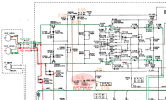
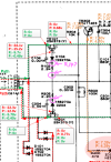
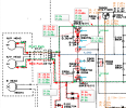
  • Look at the FET TR101 gate voltage, red voltages are the for bad deck, green are for the good deck
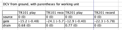
  • For the good deck, REC is -5.7v and PLAY is -0.48v, but for the bad deck REC is -24.1v and PLAY is -15.2v (both in the cutoff region)
  • In the good case, when in PLAY the Vg is -0.48v (which should turn on the FET and allow signal to pass through)
  • But, in the bad case, when in PLAY, Vg is -15.2v (which is deep into the cutoff region of the FET) causing the FET to turn-off and prevent signal from going through
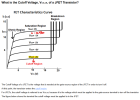
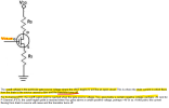
  • See the simplified JFET description below
  • Now we need to figure out why the voltages at the gate terminal of TR101/TR201 are bad in both REC and PLAY...
1725204893224.png

Let's look at how a FET works:
1725205230714.png
1725205324032.png
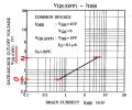
For completeness, here is the datasheet for the FET in your circuit.
1725205664281.png
1725205979403.png
Can you measure these voltages in REC and PLAY?
1725207347649.png
It also looks like Zener diode ZD301 may be bad and not zener'ing at 5.3v. You can try replacing this first then recheck voltages.
1725210029048.png
1725210079823.png
 
Last edited:
Things are getting fun now! I'm lucky that you are as stubborn tenacious as I am.
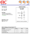
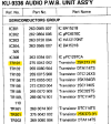
ZD301 is HZS6A1. I have already identified, but not yet ordered, possible replacements:
Mouser has MTZJ5V1SC R0 (zener v is 5.23), which ought to work.
From China I can order HZS6A2, whose zener voltage is only 0.1v higher than the original.
On eBay I can order HZS6A3, which raises that voltage by yet another 0.1v. (5.4 instead of 5.2) I'm guessing that wouldn't be a problem.
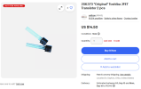
For the JFETs, there are some 2SK373 available on eBay.
I've got a brand new meter and a good reason to use it. Stick around!
 
You should be able to check the Zener in-circuit by measuring the voltage from cathode to anode in both Rec/Play to see if it limits voltage to 5.2v.
In Play, it looks like the diode is forward biased and should just act like a diode (0.7v drop).
In Rec, it might be in reverse bias since the voltage on the cathode look higher than the anode and it should clamp it to 5.3v?
 
Hi Dankik. I did a lot of measurements yesterday, but to keep things manageable, it’s probably best if I only focus on differences between the working deck and the non-working deck.

There were no significant differences when I compared, from each unit,
—The voltage drop across ZD301 (-4.7v play / -2.1v record). When I reversed the leads, I simply got +4.7 and +2.1 instead. Am I doing it wrong?
— The ground-to-cathode voltages on ZD301 (about 4.5v play / 7.4v record)
— Diodes D104 and D204, using diode check mode (in circuit) but also voltages from ground
— The voltages from ground at the junction of R102 & R202 (play 5.75v / record -7.34v)

I could find no evidence of problems with ZD301, D104, D204, R102, or R202

However, measuring from ground to the ZD301 anode in PLAY, I had 0.42v on the bad deck and only 0.10v on the good deck. That’s a difference of only 0.3v but it’s also smaller by a factor of four.

On to the critical TR101 & TR201 gate voltages, where the real anomalies are, and probably consistent with what I measured on the op-amps at the start of this whole thread.
PLAY voltages at the gate were -13v to -15v on the bad deck, 0v on the good one.
RECORD voltages at the gate were -22v to -24v (bad) and -5.81/-5.81 (good).
I have to add that I got some inconsistent results, perhaps because I needed a smaller probe.

You are probably right to say that these voltages are turning on the line mute through those two JFETs. I’m wondering where they come from and if they’ve damaged the head (it can record though) or other components I haven’t looked at.
 
Last edited:
However, measuring from ground to the ZD301 anode in PLAY, I had 0.42v on the bad deck and only 0.10v on the good deck.
The schematic says it should be R = 5.3v, P = -3.3v. I think that you previously measured -0.4v in PLAY.
PLAY voltages at the gate were -13v to -15v on the bad deck, 0v on the good one.
RECORD voltages at the gate were -22v to -24v (bad) and -5.81/-5.81 (good).
Where are these large voltages coming from??? Unless... there is something else connect to the FET gate that is not shown on the schematic???
The voltage on the other side of R102 (as you measured) are R: -7.3v/P: 5.7v
Maybe check the FET drain & source voltages also.
1725460144135.png
Can you check the PCB and see if there is anything else connected to the FET gates?
My SM isn't very good.
1725461353842.png
 
Last edited:
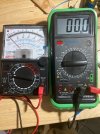
I've apparently got meter problems. I have both an analogue and a digital, both of them middle-of-the-line.
I pulled the anode of D104 out of the circuit and now I'm getting about 5v at the cathode (as before), and at the disconnected anode something like -14v. ???
So those high negative readings have been a fluke all along? That's my digital meter. The analogue meter gives me a different reading, but
the problem is that the needle barely moves when I rescale, so the reading depends on which scale I use. No good. I chose a different spot on the circuit and the meter works fine there, rescaling as expected. I'm going to look for an explanation other than voodoo.
 
Change the battery? What is the make and model of the DMM?
Are you using diode check or measuring resistance with your DMM?
With your analog meter, you should put it on resistance measurement, put the probes one way, it should show continuity and some low R, probes the opposite way should show open or high resistance. If it shows continuity in both directions, then the diode is probably bad.
 
New batteries in both meters.
I was not using diode check or measuring resistance, but only volts from ground.
I have checked D104 with diode check, and it's good. The low R forward is about .66v.
Interesting: with the anode of D104 hanging loose, the gate voltage on TR101 is still -14v if I trust my meter. But I don't!
Today has been three steps backward. We've been asking "Where is this crazy negative voltage coming from?" and the
answer seems to be "It isn't." I checked the circuit board and there is nothing else that connects. It matches the schematic.
Edit: I just ordered a new Fluke 107 meter.
My Meters.JPG
 
Last edited:
What ground reference point are you using when you checked the gate voltage?
There are actually 3 grounds:
  1. A_GND
  2. D_GND
  3. GND
They are probably all connected at some point. Is the Main board removed from the chassis when you made these measurements, or grounding wires to chassis not connected?
 
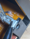
I’m mindful that you called my attention to the multiple grounds a while back. I think I even saw a HGND at some point, though I don't remember where. I’ve been measuring from W001 and W005 (see the first page of the schematic after the parts list, page 30 on my pdf). Both of them are attached to the cover, when the cover is on. I’m running a jumper between them to stand in for the cover. They’re both marked GND (photos).
> Is the Main board removed from the chassis when you made these measurements, or grounding wires to chassis not connected?
No, I have only made measurements from the upper side of the board, with those grounding wires connected and a jumper between them.
The anode of D104 is temporarily out of the circuit and giving me readings which are impossible, on both my meters. Details here.
V005.pngV001.png
 
I'm back to square one. I've put D104 back into circuit. I still get high negative voltages from chassis ground to the anode where it joins the gate of TR101. Same in the other channel at TR201. I checked the supply voltages from the power board at connector CB191 and they're right. The biggest voltage there is -20v at pin 7, but in record mode, there's -24v at TR101/TR201 gates... if that measurement is meaningful at all. Measuring across the diode in PLAY, about -12v.
 
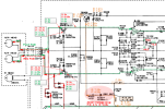
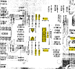
Can you please measure the DCV at these 6 points (light blue arrows) in REC & PLAY?
In your video, when you measured the DC at the anode of D104, was it in REC or PLAY?
Also, with power off, can you check the resistance between A_GND (CB141 pin 2) and where ever you connected your meter ground probe to see if they are connected?
1725924041888.png
 
Last edited:
Sure!
At the gate of TR101: Play -14.8v / Rec -24.6
At the gate of TR201: Play -13v / Rec -23v
At the junction of D104-R102-C104: Play 4.7v / Rec -6.1v
At the junction of D204-R202-C204 Play 4.7v / Rec -6.1v
At the junction of R102-R304: Play 5.7v / Rec -7.3v
At the junction of R202-R304: Play 5.7v / Rec -7.3v

For what it's worth, disconnecting D104 anode from TR101 gate did not cause the play signal on that side to come through. I had wondered if it might: I believe that the source and drain are supposed to be continuous with no voltage at the gate? However, even with D104 disconnected, my meter still showed -15.2v at the TR101 gate, both in play and record. It makes no sense to me, especially as voltages at the drain and source were all between 0v and -1v. I measured twice with the same result, but I still wonder if it's a false reading. Someone on Reddit told me not to trust standard multimeter V readings when dealing with a constant current source (TR101?) because the meter actually calculates its voltage readings based on current+internal resistance.

The fact remains that on my working version of this deck, I don't get any of these high (negative) readings.

Yes, A_GND (common from the REC/PLAY head) is continuous with chassis ground when I have a jumper between W001 and W005, but not with W001 if I remove it. Again, both these are connected to chassis screws when the cover is on, and the cover is metal, of course. I do find it weird that the designers relied on the cover to make this connection! Sorry to repeat myself. If the cover were non-conductive, of course I wouldn’t add the jumper during diagnostics.
 
My observations:
  • The voltages prior to the FET gate at the cathode of the diodes look OK, about -6v for REC and +5v for PLAY
  • But, since the diode anode voltage is always less than the cathode, no the diode will never conduct, so the diode may be OK
  • For whatever reason (either real or meter error), the FET gate voltages are way off. Also, both FETs have nearly identical bad gate voltages?
  • I would replace the two FETs and see if that fixes the gate voltages
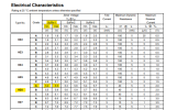
  • TR101/TR201 2SK373(Y) -- unfortunately IDK a substitute for that FET? If you look for a substitute, make sure the drain current spec is the same as "Y"
1725982879657.png
1725977851495.png
Here is the datasheet:
1725979630617.png
Hard to find? Maybe here?
1725981062786.png
 
Last edited:
Back
Top Bottom