• The move to the new server is done. There are some software and database maintenance updates in process. This has us passing the hat around to help out. We appreciate any donations. Seriously, even a dollar helps. The payment page may be found here - https://www.audiokarma.org/support.html

My Experience with Rebuilding a Marantz 1200 Integrated

MBuras

Restoration is an Addiction
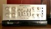
I posted here a while back that I was looking for what many considered to be the best, or their favorite, Marantz integrated amplifier. Most of the results came back either 1060 or 1200. I bought a 1060 and did an extreme rebuild on it. While I liked the general sound of it there was some oomph missing. Then I found a 1200 that needed a little help and thought what the heck. I'm in!

Although I have rebuilt probably 50-60 receivers and amps, mostly Marantz with some Pioneer, Sansui and Sony thrown in for good measure, this would be my first hands on experience with the American made Marantz models from the early 70's. And I have to say I geeked out a little on the build quality, elegant assembly, and even stunning solder work on the boards. Wow! They really knew how to build them.

So after seeing the amazing workmanship that went into this engineering feat I knew I had to do this right. No shortcuts on parts which makes things get expensive real quick. Vishay 138 AML axial capacitors all around with exceptions for out of stock values. Polypropylene films for any film capacitors replaced. I did originally think about replacing all the resistors with Vishay CMF series but the build cost went up significantly and I decided against it. Probably not enough ROI anyway.

In the posts below I'll document each board. This is only meant to be a reference for me and not a definitive guide as there are others here that are much more well versed in these models. And I'll warn here that this is not a beginner model to work on. Even with years of experience there were some moments where I had to sit back and gather my thoughts. It was challenging but fun and rewarding.
 
Register to hide this ad
First things first...fix before restoration.

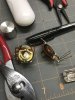
So when I bought this amplifier it was claimed to be working but the volume on one channel was crazy loud even when the volume pot was turned all the way down. I verified this experience and immediately suspected the volume pot to be at issue. I could see through the small access slots that the back half of the volume control was not moving with the front. Maybe frozen or stuck somehow?

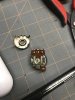
I looked around for a vintage replacement but there aren't many people parting out 1200's. Go figure!? Next option, complete volume pot disassembly, was my least favorite but what did I have to lose? It was already broken. The process wasn't as bad as I expected. A thin blade screwdriver and jewelers flat needle nose pliers were my friends. Once apart I tested both halves and each worked just fine. The tracks and wipers were in good shape so I cleaned them up while inside.

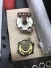
This is when I noticed the nylon insert in the rear half of the pot was stripped out. The volume knob from the front terminates in a flat metal bar at the back half and slides into this nylon insert to match front and back controls. It's a pretty sturdy piece but someone had cranked way too hard on the volume knob and completely messed it up. Not having any other options in my opinion I did the unthinkable, CA glue. Yep. A few dabs of CA in the nylon insert and then reassembly of the front shaft and pot. Let it sit for about 10 minutes and BOOM! we have an operational volume control. Front and back track together. Best solution? Maybe not. Best solution I could think of at the moment? Yes.

I resoldered the volume pot onto the interconnect board and fired everything up. And there was sound. Nice even volume tracking well up and down. The pot is a little tighter than before, probably due to my reassembly, but it works and I'm a happy camper. Gotta love the easy-ish fixes when others have given up.

Pictures of the volume pot below. As usual please ignore my messy workbench. :)

Photo Jun 12, 9 45 04 PM.jpg Photo Jun 12, 9 49 03 PM.jpg Photo Jun 12, 9 50 52 PM.jpg
 
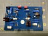
X-10 Amplifier Board

Photo Jul 11, 11 06 35 AM.jpg

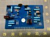
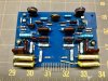
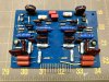
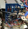
Lots of small axial caps on this board. All replaced with Vishay. Also replaced the transistors with low noise modern equivalents. The silver mica stayed in place. Super expensive and decided replacing with modern films may change the sound too much. But I'm open to future improvements.

Photo Jul 12, 9 10 46 AM.jpg
 
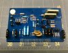
Tone Amplifier Board

Photo Jul 11, 9 34 05 AM.jpg

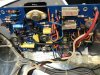
A few axial e-caps and a few films. E-caps were replaced with Vishay and 1uf films are now Vishay/Roederstein polypropylene. Again the transistors were switched out with modern low noise variants.

Photo Jul 11, 11 02 25 AM.jpg

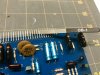
Also of note. On each of these daughter boards that plug into the main interconnect board I used a burnishing tool to polish up all sides of the metal contacts to make sure no dirt or corrosion was causing issues.

Photo Jul 11, 9 39 38 AM.jpg
 
Nice work on that pot! Sure beats having to source a replacement. My daily driver for vinyl is a 1200 that Bob Speece restored for me early this year. I considered tearing into it, but it had a loud hum and no music, so I chickened out. He did a beautiful job and I love the sound with my vinyl. Looking forward to watching your progress!
 
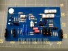
Phono Amplifier Board

Photo Jul 12, 12 03 16 PM.jpg

Once again a few axial e-caps, replaced with Vishay, and a four films, this time replaced with Panasonic polypropylene films. I wanted to use the other Vishay models but didn't order enough (DOH!) so used what I had. They don't look as nice but I like their quality. And same as on the previous boards all transistors were replaced with modern low noise equivalents.

Photo Jul 12, 12 58 53 PM.jpg
 
Power Supply Board

Photo Jul 10, 5 39 36 PM.jpg

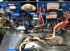
This board is where the majority of the big axial e-caps reside. All replaced with Vishay. I briefly thought about replacing the two zeners as preventative maintenance but didn't have enough confidence I chose the right replacement. The board works fine so I'll leave it for now.

Photo Jul 17, 7 44 18 AM.jpg

Apologies for the poor finished shot but I forgot to take one until everything was installed. It faces the transformer and isn't easy to see after the fact.
 
Rectifier/Relay Board

Photo Jul 10, 8 43 54 AM.jpg

I did not get the after shot of this board. Sorry. But it only has 3 axial e-caps all replaced with Vishay. And I did replace the original, open frame relay with a modified Omron MY2 as documented in this thread by Bob. Thanks for the info! It was super informative and a nice little project.
 
Power Amplifier Board (x2)

Photo Jul 14, 8 48 17 AM.jpg

Only a few axial e-caps here replaced with Vishay. And a few small value films replaced with modern polypropylene. Everything was working as expected so no replacements of transistors. Just regreasing and new mica on the outputs.

Photo Jul 14, 10 24 54 AM.jpg
 
Filter Caps

Photo Jul 14, 10 29 52 AM.jpg

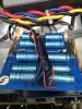
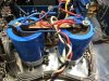
And of course these monsters! I think they're 60mm wide give or take a few. Originals were 60v/20,000uf. The replacements are 100v/22,000uf Vishay with gigantic ripple current numbers. They'll definitely do the job.
 
Cleaning the terminals on the back plate.

I usually polish the terminals on the backplate since learning about Flitz metal polish from member rBuckner. But in this case the before and after was simply amazing! I never thought the corrosion would come clean. Nice to be proven wrong.

Photo Jul 14, 1 32 45 PM.jpg Photo Jul 14, 1 32 48 PM.jpg Photo Jul 14, 1 41 40 PM.jpg Photo Jul 14, 1 41 44 PM.jpg
 
Geez, when I said I was looking forward to following the restore, I didn’t know it would be a twenty minute restore. Lol. Beautiful work!
 
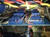
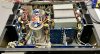
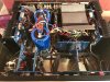
And of course there has to be a before and after photo for the inside.

Photo Jul 10, 8 16 44 AM.jpg Photo Jul 17, 7 44 40 AM.jpg

I think everything turned out really well. Bias and offset were easily adjusted within spec. Power output test didn't show and anomalies.

A few pitfalls that someone without much experience might want to look out for:
-none of the boards appear to be identified (I matched layout from the service manual)
-none of the boards have component markings (non transistor pinout, no capacitor polarity)
-axial capacitor polarity is a little different to get used to (I had to double check a few times)

Now it's time for the fun part - hooking it up to my main listening system and cranking some tunes. Whoo-hoooo!!!

Photo Jul 15, 9 43 55 AM.jpg
 
Geez, when I said I was looking forward to following the restore, I didn’t know it would be a twenty minute restore. Lol. Beautiful work!

Haha!! I know, right? I was a bit nervous about running into problems with this one so I decided to wait til the end to post anything. With no markings on the boards and little documented information on replacement parts it was challenging at time. Tested my ability to use the search engine on AK. :)

Thanks for the kind words. I look forward to breaking it in and seeing how it sounds with reference material.

Mike
 
Nice work - I am jealous

Does it sound better though?

Thanks! I can’t really say if it sounds better because I never tested it on my main system before the recap, just my shop speakers. It definitely sounded a little thinner than I expected on the shop speakers.

Just as a fun little exercise I tested each capacitor I took out. I stopped checking when I realized every one was between 3-8 ohm esr and between 3-12% leakage using a small battery tester. The Vishay 138 AML series is much better spec than that.
 
I need help with my 1200 bias adjustment. I don’t have a “watt meter” and not sure about pulling boards off heatsink to make adjustments. I think I have to remove the output transistors to do so, then it does not seem it would work to get reading?

And then I need to tackle the dc offset... any advice from someone that works on the 1200 appreciated.

45BF5DBA-638D-4025-9391-73A83CFCC11F.png 3DA5872C-13FA-4C91-9EAB-2C24B2FC63BE.png
 
Back
Top Bottom