• The move to the new server is done. There are some software and database maintenance updates in process. This has us passing the hat around to help out. We appreciate any donations. Seriously, even a dollar helps. The payment page may be found here - https://www.audiokarma.org/support.html

My first ever restauration of my good old Sansui AU-717.

PoorEars

New Member
I’m the first owner of an 40 year old AU-717.
I’ve enjoyed my Sansui for years until it started switching off and on.
It was sent to a “Sansui repair shop”.
Funny though: after switching it on, it worked but the little red led kept on blinking.
A few years later, it started to hum.
A friend knew a guy who knew a guy who knew someone in Utrecht (150 km from where I live) who did repairs on audio stuff.
So, the second repair took place.
The hum was gone.
I was satisfied and had music again.
That all happened some 20 years ago.
The past few years the volume sometimes went way up without any reason.
We found a workaround. We left the amplifier switched on day and night. Doing so gave the least chance of sudden changes in volume.
The blinking LED in mind, I didn’t trust “audio-repair-men” or woman anymore.
That lasted until I retired and had more time for things that should have taken care off for a long time.
On my list was the AU-717. Sansui and glue was an item I learned about some time ago.
And so, I stumbled across Audiokarma and I read what Leestereo did in this thread: https://audiokarma.org/forums/index...estoration-upgrade-of-a-sansui-au-717.641945/
Reading why he replaced parts gave me confidence (at last) .
Here’s a guy who knows what he’s doing, why he’s doing it and what the consequences of it are.
In the thread he explains his choices in great detail and defends them with data.
So, I made an account on Audiokarma and sent him a message.
In it I told him about the AU-717 problems (except from the details of the repairs because I found the according paperwork after I finished the restauration and wanted to know the what I payed for the amplifier back then) , my knowledge of electronics (very, very rudimentary) and asked him if he would help me getting the AU-717 in good, reliable working order.
He did.
It took 24 emails with Leestereo to get my AU-717 back to life.
And how!
It’s cured of all problems and sounds even better than ever before.
I would like to thank Audiokarma and their members for the work they do. It enabled me to get my amplifier repaired.
And a very big thanks to Leestereo.
Leestereo did a wonderful job. My email questions were answered in no-time.
It wasn’t only answering my questions but also giving valuable, much appreciated tips/hints and thinking ahead.
He knew what “problems” I might encounter end tackled them beforehand.
In the coming days I’ll post how I've worked and what was done with each board.
Total repair time: 8 days (Yep. Old, slow, doubtful and unexperienced but confident in a happy end).
 
Register to hide this ad
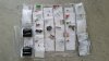
I gave the plastic bags the same number as in Mouser’s packing list and checked for possible mistakes and correct amounts.
All was ok.
 

Attachments

  • 20190918_114927.jpg
    20190918_114927.jpg
    68 KB · Views: 238
Leestereo provided me with a list of parts from Mouser.
I gave the plastic bags the same number as in Mouser’s packing list and checked for possible mistakes and correct amounts.
All was ok.
 

Attachments

  • 20190918_114927.jpg
    20190918_114927.jpg
    68 KB · Views: 27
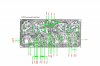
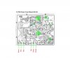
From the Sansui repair manual I copied the schematics and colored the parts that needed to be replaced. In addition I gave them the same number as the number on the plastic bags. This was done in Photoshop. I made layers of each entry and giving those layers the same name as the new parts In Photoshop you can flip the picture horizontally. The layers can be toggled “on”and “off”. This way it’s easy to find the parts on the component and copper side. Leestereo had sent me an Excel spreadsheet in which he’d listed all parts per board. In that spreadsheet I gave these parts the appropriate Mouser plastic bag number. This way I had a workable check if I had the right part from the right bag and the right place on the board.
Leestereo urged me to use a Dim Bulb Tester (DBT) between every board revision. Also ethyl acetate (e.g. non-acetone nail polish remover), to be used with a wooden or plastic scraper for removing the glue residue on the board.
That ethyl acetate was also used to clean the copper side with a soft brush after completing the replacements.
The drawback was that I ended up with a somewhat sticky board (because of the dissolving protective lacquer on the copper side?).
Leestereo’s advise to use Windex (Glassexwhere I live) to clean the component side did the trick.
After a good brush with Windex on the component and copper side, a thorough rinse with potable water and careful drying, the boards are like new and don’t stick anymore.
Good ventilation is advised when working with ethyl acetate!
I used the same workflow as Leestereo did in his thread:
F-2663 Power Supply & Protector Circuit Board, followed by
F-2720 Tone Control Circuit Board,
F-2721 Driver Circuit Board (L-CH),
F-2722 Driver Circuit Board (R-CH),
F-2723 Equalizer Circuit Board and
F-2670 Pre-Main Switch Circuit Board.
 
The following pictures are .jpg's of the schemes in the repair manuals. The original Photoshop .psd files are rather big so I converted them to jpg's
 

Attachments

  • F-2663.jpg
    F-2663.jpg
    87.6 KB · Views: 100
  • F-2720.jpg
    F-2720.jpg
    83.1 KB · Views: 92
  • F-2721.jpg
    F-2721.jpg
    67.8 KB · Views: 82
  • F-2722.jpg
    F-2722.jpg
    68.4 KB · Views: 81
  • F-2723.jpg
    F-2723.jpg
    65.8 KB · Views: 87
Things I used :
. cotton swabs, stolen from my wife’s beauty case.
. Weller soldering apparatus (with the possibility to use different tips) 24V 50Watt
. Old fashioned soldering tin: 1.3mm, 60/40 with resin.
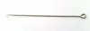
. My super handy self-made small hook (made from a stainless steel welding rod: see picture).
. A small pointed plier (also used to slide off the plastic buttons of the switches. There’s no glue used!)
. A well-fitting phillips screwdriver (Sansui has used just one size and type of self-tapping screws in the amplifier so you can keep them all in one jar).
. A small allen key to remove the knobs on the front.
. My wife’s hairdryer (for drying the rinsed boards at an appropriate distance. Maximum hand warm!!)
. A solder sucker (and stopped using it because, in time, the solder from inside the sucker tends to fall back to the print, thus making a mess and spreading old solder on the print side with the risk of shorts).
. Desoldering wick (size .075” Did a great job. Nice and clean desoldering).
. Electrically non-conductive thermal paste (used on F-2721 and F-2722).
. A Fluke 85-III DMM.
. the Dim Bulb Tester.
 

Attachments

  • Hook.jpg
    Hook.jpg
    13.1 KB · Views: 38
So my AU-717 has undergone two previous “repairs”. Those two turned out have some surprises in store.
Removing the first board, F-2663, from the chassis was quite easy.
A few wires has to be desoldered. Sansui used a kind of spring-released soldering clamps that can cause problems.
They have more solder on them, thus have a greater mass and therefore absorb more heat.
Too much heat will cause the copper of the board’s print to loosen.
While pulling the leads out of the board, you wouldn’t notice anything. It’s the replacing that turns out to be tricky.
Using force while pushing those leads back in place it the worst thing to do.
The trick is to get rid of all solder on the pins and pinch the front a bit so they fit easily into the hole.
My predecessors should have done the same.............
 
This is what the board looks like after restauration, Glue removed, board cleaned on both sides, new parts installed including the new relay.
Leestereo advised to check the transistors for bad solder joints.
I had the feeling that he was looking over my shoulder and saw things I had missed.
He was right.
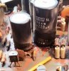
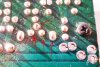
So: I gave the four of them a thorough inspection, and yes. Some of the transistors needed more attention than I fist thought
So: I had to scratch the protective paint until I had nice, clean copper to
to reinforce the connections
 

Attachments

  • F-2663 After restauration01.jpg
    F-2663 After restauration01.jpg
    84.6 KB · Views: 87
  • F-2663 After restauration02.jpg
    F-2663 After restauration02.jpg
    80.5 KB · Views: 82
  • Bad joints.jpg
    Bad joints.jpg
    119.7 KB · Views: 83
Last edited:
After the board was back in place and connected, it was time for the first test.
The Dim Bulb Tester came into action, the power LED started blinking for a few nerve-wrecking seconds and: click.
All seemed well. I connected my headphones to the jack in front of the AU-717 and my MP3 player to the AUX input.
Besides music I heard a hum.
An undeniable hum.
The relief came from Leestereo’s mail: “As for the hum, are all of the metal shields in place when it occurs”.
Right again!
 
Next board to do: F-2720.
Did someone reenforce a joint?
Had to be careful with the cleaning procedure to prevent the solvents spoiling the switches.
I didn’t want to introduce problems with them because they did a good job during 40 years.
After replacing and connecting the board: testing with the Dim Bulb Tester and do some listening.
Seeing the power-on LED blink at first, the click and then the LED switching to "on" gave (and still gives) great satisfaction.
 

Attachments

  • F-2720 component before.jpg
    F-2720 component before.jpg
    102.5 KB · Views: 74
  • F-2720 copperside before.jpg
    F-2720 copperside before.jpg
    94 KB · Views: 74
  • F-2720 component after.jpg
    F-2720 component after.jpg
    104.8 KB · Views: 77
Friend, you have done an outstanding job here, right from the early period of its symptoms, to sourcing the help of the first tech and then seeking a wise AKer LeeStereo. You have systematically embarked on an all out recap on a high quality piece, done with basic prior skill and knowledge in electronics. Your photos speak for themelves and so to the descriptions of you methods. It's of no surprise that this amp is again performing as it should, you should be well satisfied with your efforts, great job!!!
 
Next F-2721 and F-2722 and a surprise again.
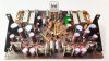
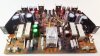
I first did F-2721. Cleaning and replacing compomnents was somewhat "routine".
But with F-2722 I noticed a missing resistor.
It was quite obvious that a repair had taken place.
But what were the consequences?
My doubts were shared with Leestereo.
He checked the scheme and came to the conclusion that the effect of the change was not noticeable. So we left it “as is”. Besides of the missing resistor, there are more, small, differences between the boards. There’s a difference in the amount of spacers applied. One would expect them to be less at the board with the missing resistor but the opposite is true. Strange. Perhaps a Monday/Friday difference?
After putting both boards back into the chassis and carefully soldering the connecting wires again, Leestereo asked if I had tightened the screws on the transistor mounted on the heat sink of each board.
That’s when I knew for sure that Leestereo didn’t always see what I was doing.
I tightened them.
 

Attachments

  • F-2721 component before.jpg
    F-2721 component before.jpg
    75 KB · Views: 73
  • F-2722 component before.jpg
    F-2722 component before.jpg
    69.7 KB · Views: 65
  • Missing resistor.jpg
    Missing resistor.jpg
    101.7 KB · Views: 72
  • F-2721 component after.jpg
    F-2721 component after.jpg
    68.1 KB · Views: 69
  • F-2722 component after.jpg
    F-2722 component after.jpg
    79.4 KB · Views: 52
Time to work on F-2723, the Equalizer Circuit Board.
The same procedure as before.
Replacing components from Leestereo’s list, cleaning, drying and being careful to stay away from the switches, finishing with the DBT and listening test.
I left most of the wires connected.
 

Attachments

  • F-2723 component after.jpg
    F-2723 component after.jpg
    98.7 KB · Views: 50
  • F-2723 component before.jpg
    F-2723 component before.jpg
    100.9 KB · Views: 49
  • F-2723 copperside after.jpg
    F-2723 copperside after.jpg
    93.3 KB · Views: 48
Back
Top Bottom