• The move to the new server is done. There are some software and database maintenance updates in process. This has us passing the hat around to help out. We appreciate any donations. Seriously, even a dollar helps. The payment page may be found here - https://www.audiokarma.org/support.html

My first ever restauration of my good old Sansui AU-717.

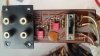
One more to do: F-2670, the Pre-Main Switch Circuit.
Replacing the two capacitors wasn’t worthwhile to making a Photoshop guide.
I bent the leads so that they fitted the appropriate holes in the board.
That, by the way, were the only parts that needed a bit of bending.
The rest fitted like glove thanks to the research LeeStereo did for the replacement.
All other parts fitted nicely, either by size or leads or their thickness.
A remarkable job considering the amount of variations in parts available.
 
You've posted 2 pictures of '2721 component after' - with one labelled as '2722 component after' :idea:
Will change tomorrow.....
Thanks for your remark, good observation! Such mistakes are deadly if you're restoring your amplifier. That's why I double, double checked every step in the process (and it lasted eight days).
 
Last edited:
Another one of LeeStereo’s tips:
At the back of the amplifiers, the boards are attached to it with plastic “knobs”.
On the inside, these things are secured with some kind of glue.
The LeeStereo's trick was to soak them with ethyl acetate.
That made the glue to dissolve enough to enable removing the small pins (the things you see outside of the backside) with a plier.
After that, it was easy removing what’s left in the chassis.
LeeStereo suspected that the sudden changes of volume might be caused by a dirty Pre-Main Switch and advised to give it a good cleaning with naphta.
 

Attachments

  • F-2670 component after.jpg
    F-2670 component after.jpg
    78.5 KB · Views: 64
  • F-2670 component before.jpg
    F-2670 component before.jpg
    63.4 KB · Views: 60
Last thing to do: replacing the capacitors in the chassis.
And that, for me, was the most confusing exercise.
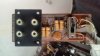
The capacitors had been replaced in an earlier “repair” because they weren’t the standard Sansui capacitors.
Because of my limited knowledge of electronics (and reading their schemes to determine what is the plus and what is the minus), I had to be sure that I didn’t screw up the whole restauration by mixing the leads.
The picture shows what I found.
 

Attachments

  • Existing mounting capacitors.jpg
    Existing mounting capacitors.jpg
    82.3 KB · Views: 70
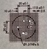
Thanks to Google I found documentation that matched the installed type. In the upper right corner “my type”.
The capacitors that I got via LeeStereo’s list were marked with a clear “+” and “-“.
In order to be sure I had the right documentation I even scaled the component side of the document to fit the pins of the capacitors that were installed, printed it and punched the print with the existing capacitor.
My brains (the small bit I normally use) got overheated by imagining print-side and component-side.
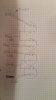
After some emails with Leestereo I was sure how to replace the capacitors without ending up with a AU-717 as a piece of junk.
 

Attachments

  • ALP tech data.jpg
    ALP tech data.jpg
    94.1 KB · Views: 53
  • Punched.jpg
    Punched.jpg
    78 KB · Views: 52
  • Drawing how.jpg
    Drawing how.jpg
    33.5 KB · Views: 51
At last: Replacing the capacitors and putting back all metal shields, the final test:
Does the DBT survive?
Is here an audible hum?
Relief, relief.
DBT was ok, and hum?
Nothing. Not even a faint little hummie.
Silence throughout het whole range of the volume.
My good old amplifier back to life.
And how!
Ah.
LeeStereo mail in the Inbox: “Also remember to use the DBT for initial adjustment of the bias with the restored driver boards.”
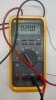
I had no insulated screwdriver to reach the potentiometers, but had some long wooden cocktail sticks and turned one into a nice fitting screwdriver.
The first two adjustments were easy to do (both left and right the same reading) but the bias adjustment was a bit tricky to get the right reading.
 

Attachments

  • Adjustments.jpg
    Adjustments.jpg
    61 KB · Views: 36
  • DC L and R channel.jpg
    DC L and R channel.jpg
    35.3 KB · Views: 34
  • Bias left.jpg
    Bias left.jpg
    37.9 KB · Views: 34
  • Bias right.jpg
    Bias right.jpg
    36.6 KB · Views: 35
Finally.
Better than before?
I don’t have a reference.
But: taking into account that LeeStereo provided me with all I needed to get my amplifier back to life again, realizing how much work it takes to select the right parts, that the amplifier had no additional strange behavior, that everything that I’ve done with LeeStereo’s help led to an normal working piece of electronics,
I can only conclude the the AU-717 indeed sounds better than before.
Perhaps even better than the day it left Sansui’s plant.
Why?
Reading on this forum that LeeStereo selected the right quality parts and the fact that those parts are of a far better quality than those 40+ years ago.
I can’t express how happy I am with my new amplifier. Flipping the “on” switch every morning with a smile, getting old fashioned goose bumps while listening to Ludwig van Beethoven’s violin concerto in D major op.61 with Isabelle Faust on violin and Claudio Abbado as conductor.
I would like to thank all on this forum for sharing their knowledge.
I realize that you all have different approaches and views about Sansui restorations.
The one that helped me enormously was that of LeeStereo.
I’m convinced that anyone who only knows two things: how to hold a soldering iron and that you mustn’t overheat electronic parts (that is my knowledge on the matter), can restore an amplifier like mine with no major problems with LeeStereo’s part lists and help.
I would like to thank him gratefully for how he helped me. Patient, to the point, thinking with me and ahead of me (most times).

Chapeau LeeStereo!

:trebon:
 
Thanks for the kind words. Very nice pictures and write-up; seems that you enjoyed the restoration/upgrade process and can now fully enjoy your 717 once again!
Yep. It was a nice and in hindsight easy experience that was worthwhile every single minute.
 
index.php
 
One more to do: F-2670, the Pre-Main Switch Circuit.
Replacing the two capacitors wasn’t worthwhile to making a Photoshop guide.
I bent the leads so that they fitted the appropriate holes in the board.
That, by the way, were the only parts that needed a bit of bending.
The rest fitted like glove thanks to the research LeeStereo did for the replacement.
All other parts fitted nicely, either by size or leads or their thickness.
A remarkable job considering the amount of variations in parts available.
Nice job! By the way, I dont think you needed to bend those leads if you placed them where leestereo did, namely, where C05 and C06 are.
 
Back
Top Bottom